Electro-hydraulic brake system

A hydraulic braking and electronic technology, applied in braking control systems, brakes, brake components, etc., can solve problems such as hidden dangers in reliability and safety, leakage of nitrogen gas from high-pressure accumulators, etc., to achieve good braking feeling, The effect of fast response and reduced axial dimension

Inactive Publication Date: 2015-01-28
TONGJI UNIV
View PDF8 Cites 32 Cited by
  • Summary
  • Abstract
  • Description
  • Claims
  • Application Information

AI Technical Summary

Problems solved by technology

[0005] Most of the current electronic hydraulic braking systems use motors, pumps and high-pressure accumulators as power sources. However, there is a danger of nitrogen leakage in high-pressure accumulators, and there are still hidden dangers in reliability and safety.

Method used


Image

  • Electro-hydraulic brake system
  • Electro-hydraulic brake system
  • Electro-hydraulic brake system

Examples


Embodiment Construction

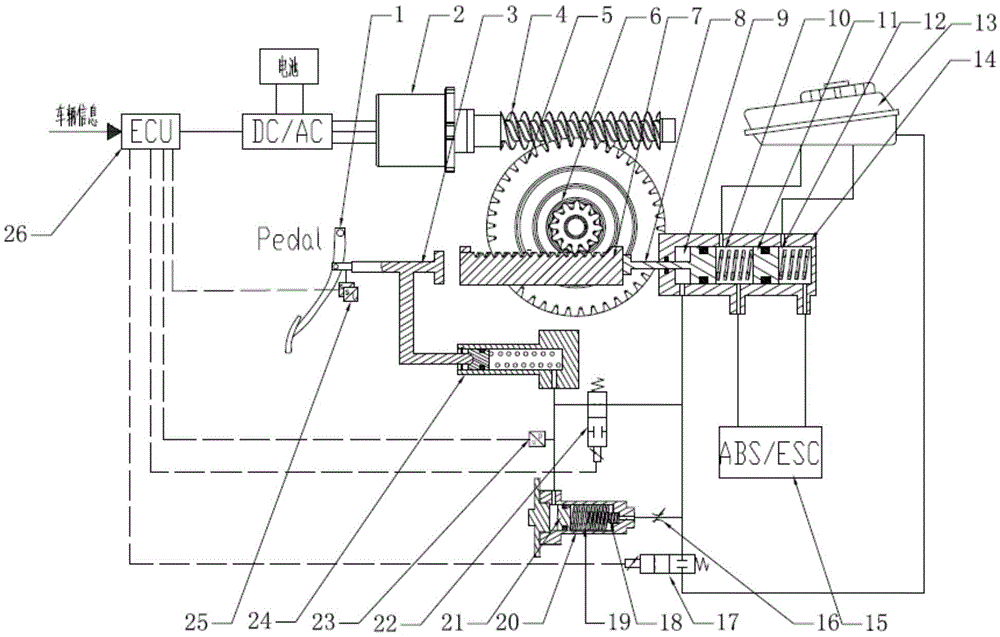
[0049] like figure 1 As shown, a motor-driven electro-hydraulic braking system includes:

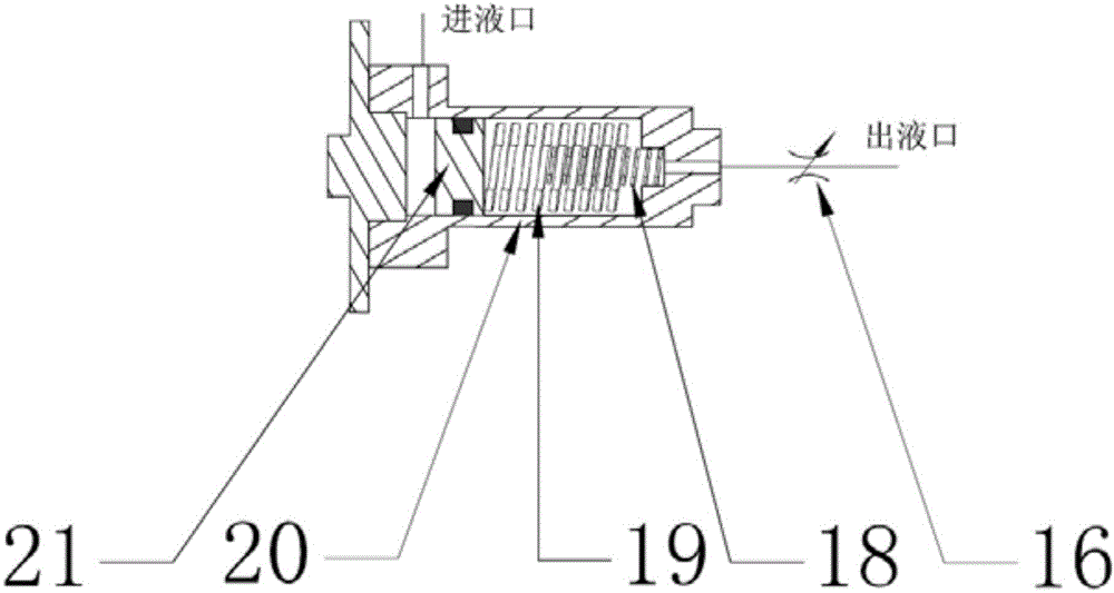
[0050] Brake pedal 1, a pedal displacement sensor 25 for obtaining the displacement of the driver's depressing the brake pedal, a hydraulic pressure sensor 23 for judging the driver's braking intention, a liquid storage tank 13, and a sensor for simulating the pedal braking feedback force pedal simulator 20;

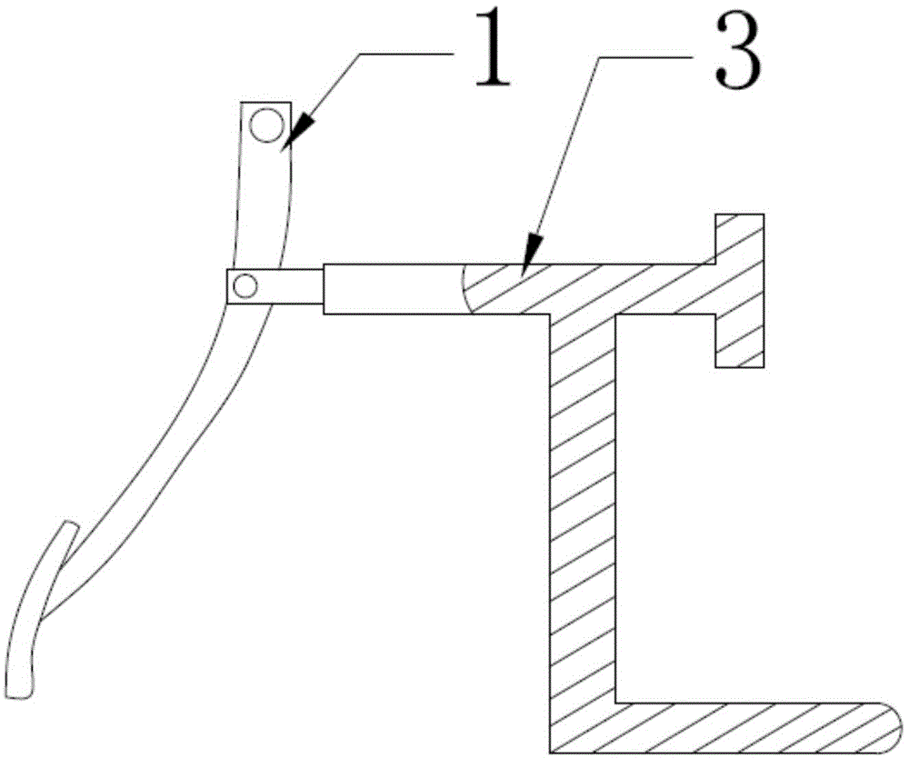
[0051]A brake pedal push rod 2 with two branches connected to the brake pedal 1, one of the branches of the brake pedal push rod 2 is set against the linear motion mechanism, a certain gap is reserved between the two, and it is connected with the brake master cylinder 14 The pistons are located on the same axis, so that when the motor fails, the driver’s pedal force can drive the rack or lead screw to move forward, pushing the master cylinder piston to generate braking force; the other branch of the brake pedal push rod 2 is connected to the secondary master cylinder 24 connected...


PUM


Abstract

The invention discloses an electro-hydraulic brake system driven by a motor for a vehicle. The electro-hydraulic brake system comprises a brake pedal, a pedal displacement sensor, a hydraulic sensor, a pedal simulator, a pedal push rod with two branches, an electric control unit, an electric control linear motion module, a brake main cylinder, a secondary main cylinder and an ABS (anti-lock braking system) / ESC (electronic stability control) module; one branch of the pedal push rod is abutted against the linear motion mechanism, and is positioned in the same axis as the piston of the brake main cylinder; the other branch of the pedal push rod is connected with the piston of the secondary main cylinder; the brake main cylinder sequentially comprises a front cavity, a first cavity and a second cavity for the brake main cylinder; the front cavity is connected with the secondary main cylinder and a liquid storage tank respectively through a decoupling valve and a liquid supply valve; the first cavity and the second cavity are connected with a vehicle wheel brake through the ABS / ESC module; the secondary main cylinder is connected with the liquid inlet of the pedal simulator. The electro-hydraulic brake system is used for recycling brake energy, improving system response time and accurately controlling hydraulic brake force, well feeds the braking force back to a driver, and realizes active control over hydraulic force and pedal force of the system.

Description

technical field [0001] The invention belongs to the technical field of automobiles, and relates to automobile braking technology, in particular to an electronic hydraulic braking system driven by a motor. Background technique [0002] There are two trends in the development of automobiles today: electrification and intelligence. The electric vehicle is equipped with a high-power drive motor. When the vehicle decelerates and brakes, the motor's drag is used to reverse the power supply to generate a reverse electromotive force, which turns the motor into a generator for power generation, and converts the kinetic energy of the vehicle into electrical energy storage. into the battery, namely regenerative braking (also known as braking energy recovery). These stored electric energy can greatly increase the driving range of the car, and change the disadvantages of low driving range and large battery size of electric vehicles. Today, when the battery technology is not perfect eno...

Claims


Application Information

Patent Timeline
Patent Type & Authority Applications(China)
IPC IPC(8): B60T13/68B60T13/12
CPCB60T13/686B60T13/12B60T2220/04B60T2270/602
Inventor 余卓平广学令熊璐侯一萌徐松云
Owner TONGJI UNIV
Why Eureka
Try Eureka