System and method for controlling an electric arc welder

a technology of electric arc welding and electric arc welding, which is applied in the direction of arc welding apparatus, welding apparatus, manufacturing tools, etc., can solve the problem of high current speed increase and other problems, and achieve the effect of preventing any current overshoot and rapid response tim

Inactive Publication Date: 2002-12-24
LINCOLN GLOBAL INC
View PDF8 Cites 141 Cited by
  • Summary
  • Abstract
  • Description
  • Claims
  • Application Information

AI Technical Summary

Benefits of technology

The problems experienced in using a slow outer control loop with or without a high speed inner current control loop, as explained above, have been overcome by the present invention which essentially uses only the inner high speed loop for controlling the welding process. This is made possible by utilizing both the sensed arc current and the sensed arc voltage to produce a feedback signal indicative of the current and voltage product, i.e. power. Essentially, the electric arc welding process, whether it is spray, pulse or AC, has the actual arc power controlled by the desired power. To accomplish this result, both the sensed current and the sensed voltage are used. In the past, the arc voltage controlled the outside loop with its slow response time. The inner high speed loop was merely a current responsive feedback system where a digital error amplifier adjusted the input to the pulse width modulator driving the high speed switching power supply. By utilizing the product of the actual output current and voltage feedback signals, the actual output watts or power is sensed. This signal P is compared to the desired power established by the wave shaper. This causes the output current to change in a manner that forces the actual power to equal the desired power. This is performed at a speed generally ten times as fast as an outer loop control. By using a feedback signal based upon a relationship between both the current and voltage, the arc length is automatically adjusted and the rapid response time prevents any current overshoot.

Problems solved by technology

This causes an immediate high speed increase in the current.

Method used


Image

  • System and method for controlling an electric arc welder
  • System and method for controlling an electric arc welder
  • System and method for controlling an electric arc welder

Examples


Embodiment Construction

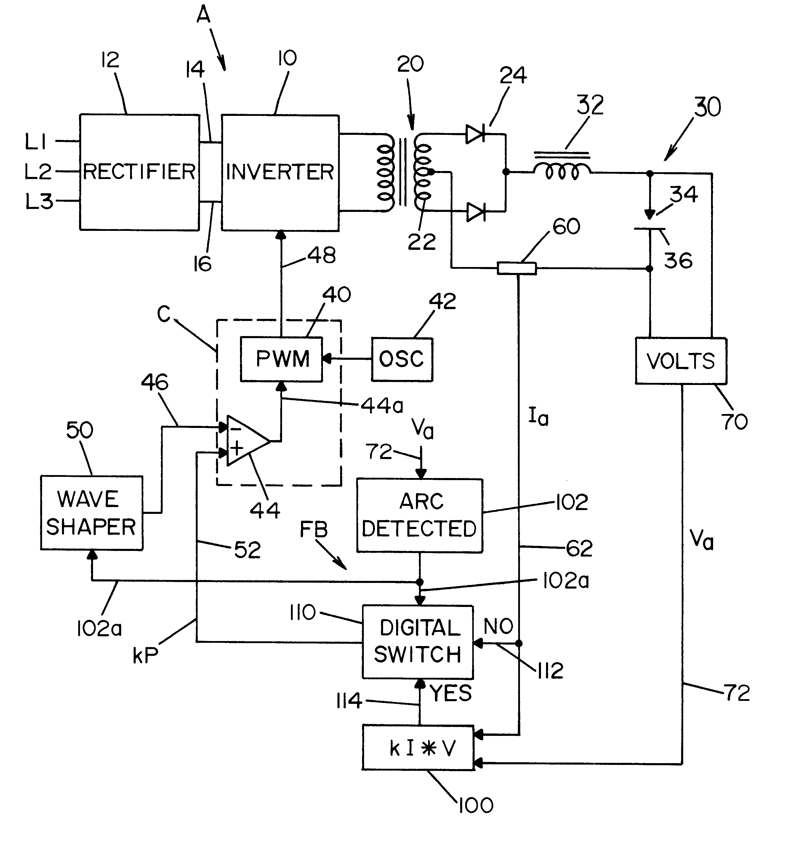
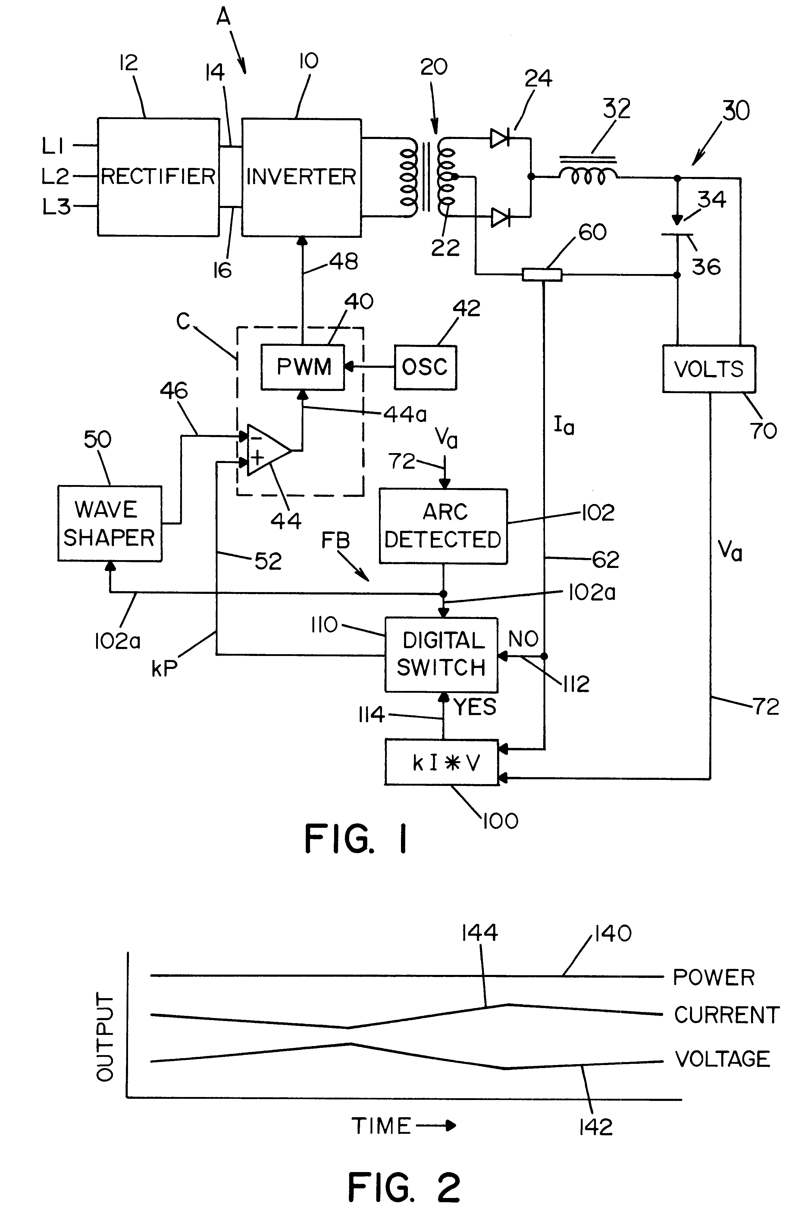
Referring now to the drawings wherein the showings are for the purposes of illustrating preferred embodiments of the invention only, and not for the purpose of limiting same, FIG. 1 shows a welder A to perform a preselected welding process by using a high speed switching type power supply 10, illustrated as an inverter, but it could be a high speed switching chopper. In accordance with standard technology, the switching speed of the power supply is over 10 kHz, and preferably over 18 kHz. Inverter 10 is provided power from three phase rectifier 12 across a DC link in the form of input leads 14, 16. Output transformer 20 includes a center tapped secondary 22 driving output rectifier 24 for performing a welding process in output circuit 30 including an inductor 32 and an electrode 34 forming an arc gap with workpiece 36. In practice, electrode 34 is a forward advancing welding wire from a supply spool driven toward workpiece 36 during the performance of the welding operation. A wire f...


PUM

PropertyMeasurementUnit
switching frequencyaaaaaaaaaa
currentaaaaaaaaaa

Abstract

A control system for an electric arc welder performing a welding process between an electrode and a workpiece, which system comprises: a high speed switching type power supply with a controller operated at a switching frequency of at least about 10 kHz with an input current control signal to adjust the output current of the power supply; a first sensor sensing the actual arc voltage; a second sensor sensing the actual arc current; a first circuit for creating a power signal representing the desired real time power level at progressive times during the welding process; a second circuit for creating a function of the sensed actual voltage and the sensed actual current; and a third circuit for adjusting the current control signal in accordance with the difference between the power signal and the function of the actual voltage and current, preferably arc power.

Description

The present invention relates to the art of electric arc welding and more particularly to an improved system and method for controlling the power supply during a welding process.BACKGROUND OF INVENTIONIn electric arc welding it is common to employ a high speed switching type power supply, such as an inverter or chopper, so the output current of the power supply can be adjusted by a high speed control loop involving current feedback. In such electric arc welders, there is an outer control loop for creating the current command in accordance with the comparison of the average arc voltage with a reference voltage. In some instances, the current command signal to the power supply is directly controlled by the outer control loop. Consequently, the inner high speed control is based upon current feedback and is adjusted to maintain an average voltage. These inner high speed control loops operate at somewhat close to the speed of the inverter or chopper. The outer voltage control loop operat...

Claims


Application Information

Patent Timeline
Patent Type & Authority Patents(United States)
IPC IPC(8): B23K9/10B23K9/073B23K9/09B23K9/095H02M9/00
CPCB23K9/1056B23K9/09
Inventor FULMER, BRUCE E.PETERS, STEVEN R.
Owner LINCOLN GLOBAL INC
Why Eureka
Try Eureka