Controller-integrated rotating electrical machine

a technology of integrated control and rotating electrical machines, which is applied in the direction of cooling/ventilation arrangement, association with control/drive circuits, and association for rectification, etc., can solve the problems of increasing the inability to cool the rear bearing in the vicinity of the center of the rotation shaft, and the inability to detect the position of the pole position sensor, so as to reduce the axial dimension of the rotating electrical machine and enhance the cooling performan

Active Publication Date: 2013-12-05
MITSUBISHI ELECTRIC CORP
View PDF16 Cites 31 Cited by
  • Summary
  • Abstract
  • Description
  • Claims
  • Application Information

AI Technical Summary

Benefits of technology

[0007]The invention is devised to solve the problems discussed above and has an object to provide a controller-integrated rotating electrical machine capable of not only enhancing cooling performance for a magnetic pole position detection sensor and a brush holder, but also reducing an axial dimension of the rotating electrical machine.
[0009]When configured in this manner, a temperature of the switching devices can be lowered by cooling the heat sink of the inverter apparatus with the first cooling air, and moreover, because an inner peripheral side surface of the inverter apparatus, the brush holder, and the magnetic pole position sensor can be cooled with the second cooling air flowing into the hollow portion of the inverter apparatus from the axially rear thereof, temperatures of the inverter apparatus, the brush holder, and the magnetic pole position detection sensor can be lowered, too.

Problems solved by technology

This configuration raises a problem that a magnetic pole position detection sensor, a brush holder, and a rear bearing disposed in the vicinity of a center of a rotation shaft cannot be cooled sufficiently.
This configuration raises another problem that an axial dimension of the rotating electrical machine is increased and so is a size of the rotating electrical machine.

Method used


Image

  • Controller-integrated rotating electrical machine
  • Controller-integrated rotating electrical machine
  • Controller-integrated rotating electrical machine

Examples


first embodiment

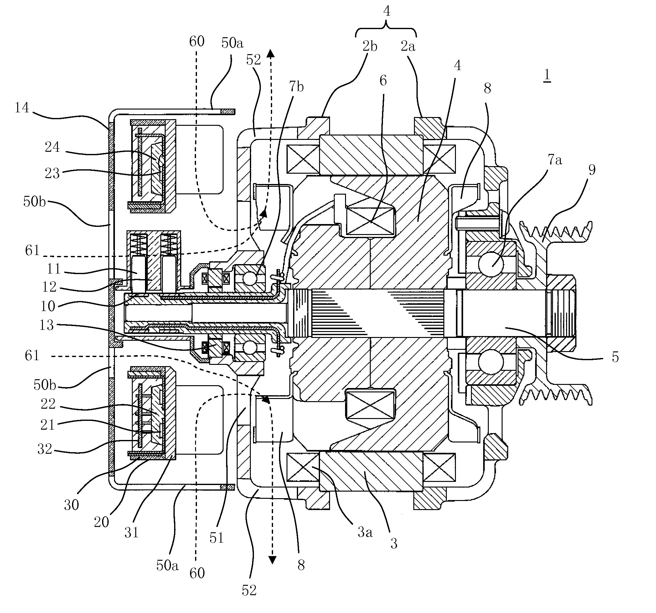
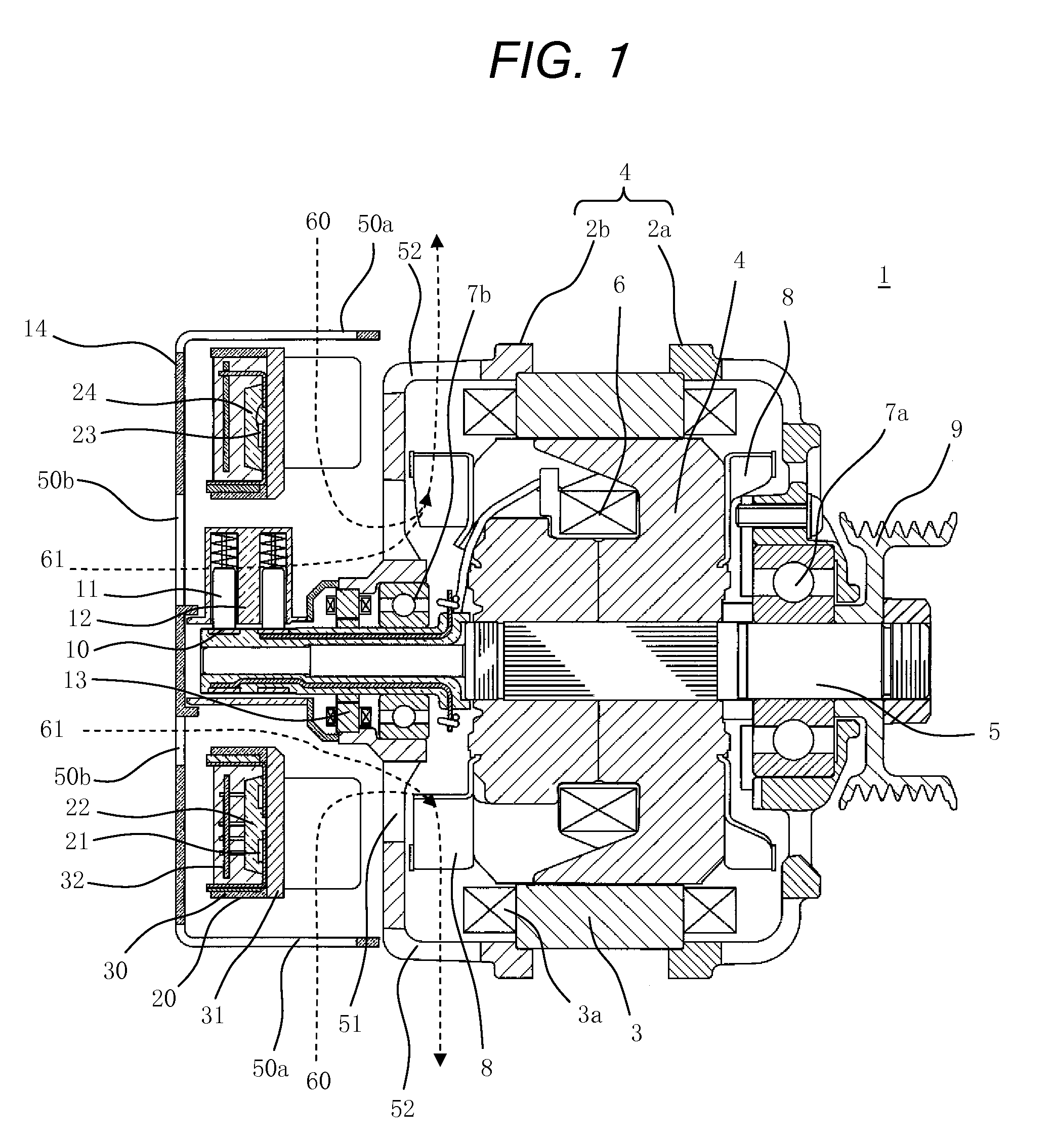
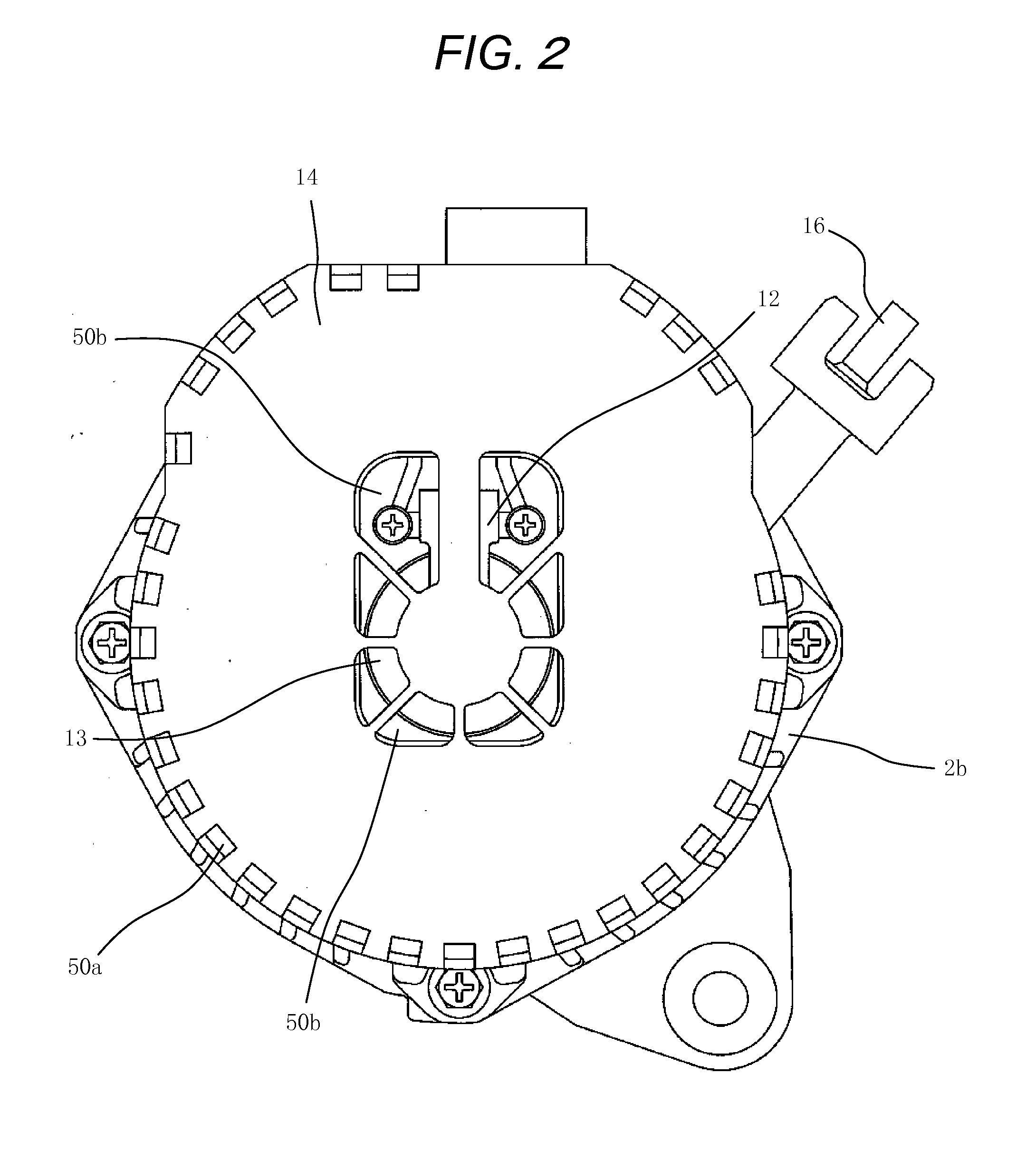
[0022]FIG. 1 through FIG. 11 are views showing a controller-integrated rotating electrical machine according to a first embodiment of the invention.

[0023]Referring to the drawings, a rotating electrical machine 1 includes a housing 2 formed of a front bracket 2a and a rear bracket 2b, a stator 3 having armature windings 3a, and a rotor 4 having a rotation shaft 5 and field windings 6. The stator 3 is fixedly supported on one end portion of the front bracket 2a and one end portion of the rear bracket 2b and the rotor 4 is disposed on the inside of the stator 3.

[0024]The rotation shaft 5 is supported in a rotatable manner on a front bearing 7a and a rear bearing 7b provided to the housing 2 and the rotor 4 is allowed to rotate concentrically with the stator 3.

[0025]Cooling fans 8 are fixed onto both axially end faces of the rotor 4. A pulley 9 is attached to the rotation shaft 5 at an end portion on a front side (on the outside of the front bracket 2a) and a pair of slip rings 10 is a...


PUM


Abstract

A first cooling air passage is formed to let first cooling air generated by a cooling fan in from a radially outside of an inverter apparatus to cool a heat sink and out through exhaust holes provided on an outer peripheral side of a rear bracket by passing an inner periphery of the rear bracket. Also, a second cooling air passage is formed to let second cooling air generated by the cooling fan into a hollow portion of the inverter apparatus from an axially rear of a rotation shaft to cool a brush holder and a magnetic pole position detection sensor and out through the exhaust holes by passing the inner periphery of the rear bracket. Hence, cooling performance for the magnetic pole position detection sensor and the brush holder may be enhanced and an axial dimension may be reduced.

Description

BACKGROUND OF THE INVENTION[0001]1. Field of the Invention[0002]The present invention relates to a controller-integrated rotating electrical machine for vehicle formed by attaching an inverter apparatus that supplies armature windings and field windings with power to a rotating electrical machine main body on an outside in a rear of a rear bracket.[0003]2. Background Art[0004]An apparatus in the related art is formed by installing an inverter apparatus incorporating switching devices and a control circuit in the rear of a rear bracket forming a rotating electrical machine main body to let cooling air in from a radially outside of the inverter apparatus and out from exhaust holes provided on the radially outside of the rear bracket by passing through vent holes provided along an outer periphery of a bearing holding portion of the rear bracket, so that a heat sink of the inverter apparatus is cooled. An example of this configuration is disclosed, for example, in JP-A-2006-33986.[0005]...

Claims


Application Information

Patent Timeline
Patent Type & Authority Applications(United States)
IPC IPC(8): H02K9/06
CPCH02K11/215H02K11/30H02K11/33H02K9/06H02K5/207H02K11/05H02K9/02H02K9/04H02K9/28
Inventor ISODA, HITOSHIUTSUMI, YOSHINOBUFUJITA, MASAHIKO
Owner MITSUBISHI ELECTRIC CORP
Why Eureka
Try Eureka