

Dual clutch automatic transaxle
- Summary
- Abstract
- Description
- Claims
- Application Information
AI Technical Summary
Benefits of technology
Problems solved by technology
Method used
Image

Examples
Embodiment Construction
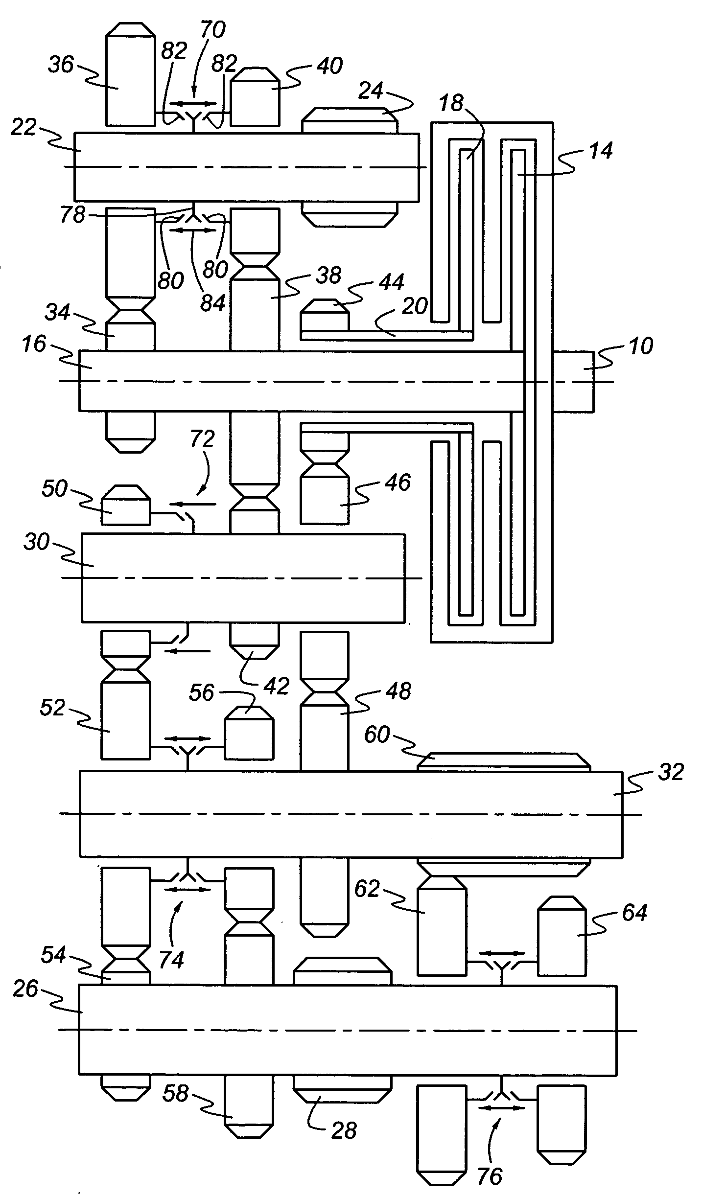
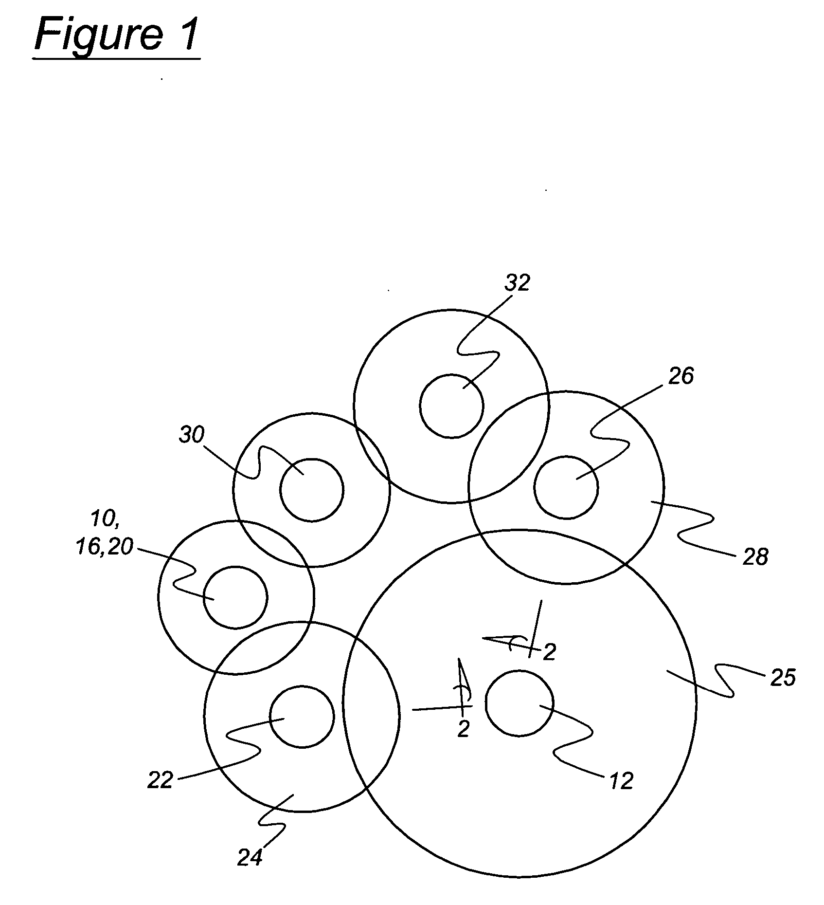
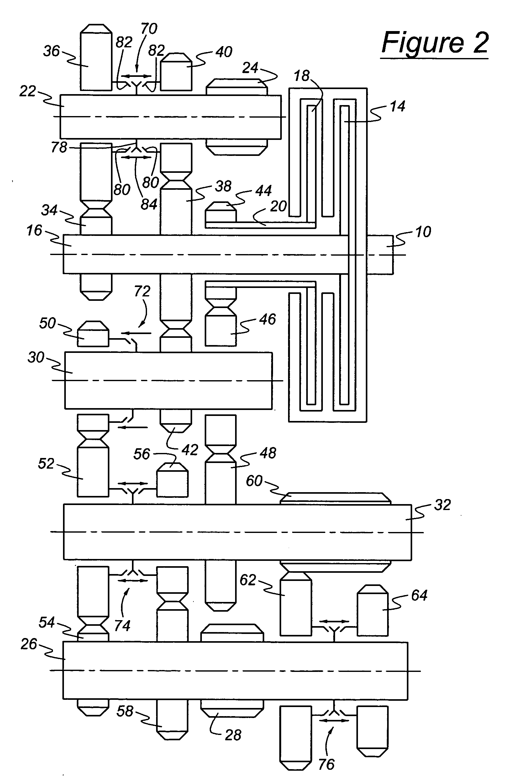
[0017] Referring to FIGS. 1 and 2, a transmission according to the present invention includes an input 10 for driveably connecting a power source, such as an internal combustion engine or electric motor, to the transmission, and an output 12 for driving a load, such as the driven wheels of a motor vehicle, through a powertrain that may include a drive shaft, differential mechanism, and axle shafts. A first friction clutch 14, consisting of a clutch housing and a clutch disc, alternately connects and disconnects a first input shaft 16 as clutch 14 is engaged and disengaged, respectively. A second friction clutch 18, consisting of a clutch housing and a clutch disc, connects and disconnects a second input shaft 20 as clutch 18 is engaged and disengaged, respectively.
[0018] A first output shaft 22 supports a first output pinion 24, which is secured to shaft 22 in continuous meshing engagement with an output gear 25, secured to output 12. A second output shaft 26 supports a second outp...
PUM
 Abstract
Description
Claims
Application Information