Vehicle

Active Publication Date: 2018-10-04
TOYOTA JIDOSHA KK +1
View PDF3 Cites 13 Cited by
  • Summary
  • Abstract
  • Description
  • Claims
  • Application Information

AI Technical Summary

Benefits of technology

[0007]In the above vehicle, the power control unit may include first voltage converter circuits and inverter circuits. The first voltage converter circuits may be configured to boost voltage of the electric power source. The inverter circuits may be configured to convert output electric power of the first voltage converter circuits to alternating current. A first capacitor may be connected between a first positive-electrode terminal and a first negative-electrode terminal that are located on the electric power source side of the first voltage converter circuits. A second capacitor may be connected between a second positive-electrode terminal and a second negative-electrode terminal on the inverter circuit side of the first voltage converter circuits. The first capacitor and the second capacitor may be disposed, in the case, on the same side in the vehicle-width direction so as to be adjacent to the stacked unit. In the above vehicle described in JP 2015-204688 A, the first capacitor is disposed adjacent to the stacked unit in the vehicle-width direction, and the stacked unit, the reactors, and the second capacitor are arranged in the stacking direction. The first capacitor and the second capacitor are arranged on the same side in the vehicle-width direction to be adjacent to the stacked unit, to thereby further reduce the length in the vehicle-longitudinal direction of the power control unit installed in the vehicle.
[0008]The above vehicle may further include: a rear motor; and an auxiliary-device battery. The motors may be for driving front wheels. The motor housing may be installed in a front compartment of the vehicle. The power control unit may further include: a rear inverter circuit; and a second voltage converter circuit. The rear inverter circuit may be configured to convert direct current electric power to drive electric power of the rear motor for driving rear wheels. The second voltage converter circuit may be configured to step down the voltage of the electric power source and provide this voltage to the auxiliary-device battery. The second voltage converter circuit may be disposed rearward of the reactors in the case. A rear motor connector connected to a rear motor power cable that sends electric power to the rear motor may be provided on a surface of the case, and the surface provided with the rear motor connector may be directed toward the rearward direction of the vehicle. An auxiliary-device battery connector connected to an auxiliary-device battery power cable that sends electric power from the second voltage converter circuit to the auxiliary-device battery may be provided on a surface of the case, and the surface provided with the auxiliary-device battery connector may be directed toward the vehicle-width direction. By providing the rear motor connector to the rear surface of the case, it is possible to shorten the rear motor cable. In addition, by providing the rear motor connector, which is provided on the lateral side surface of the case in the related art, to the rear surface, it is poss

Problems solved by technology

When the power control unit is arranged in the vehicle such that the stacking direction of the power modules and the coolers is directed toward the

Method used


Image

  • Vehicle
  • Vehicle
  • Vehicle

Examples


Example

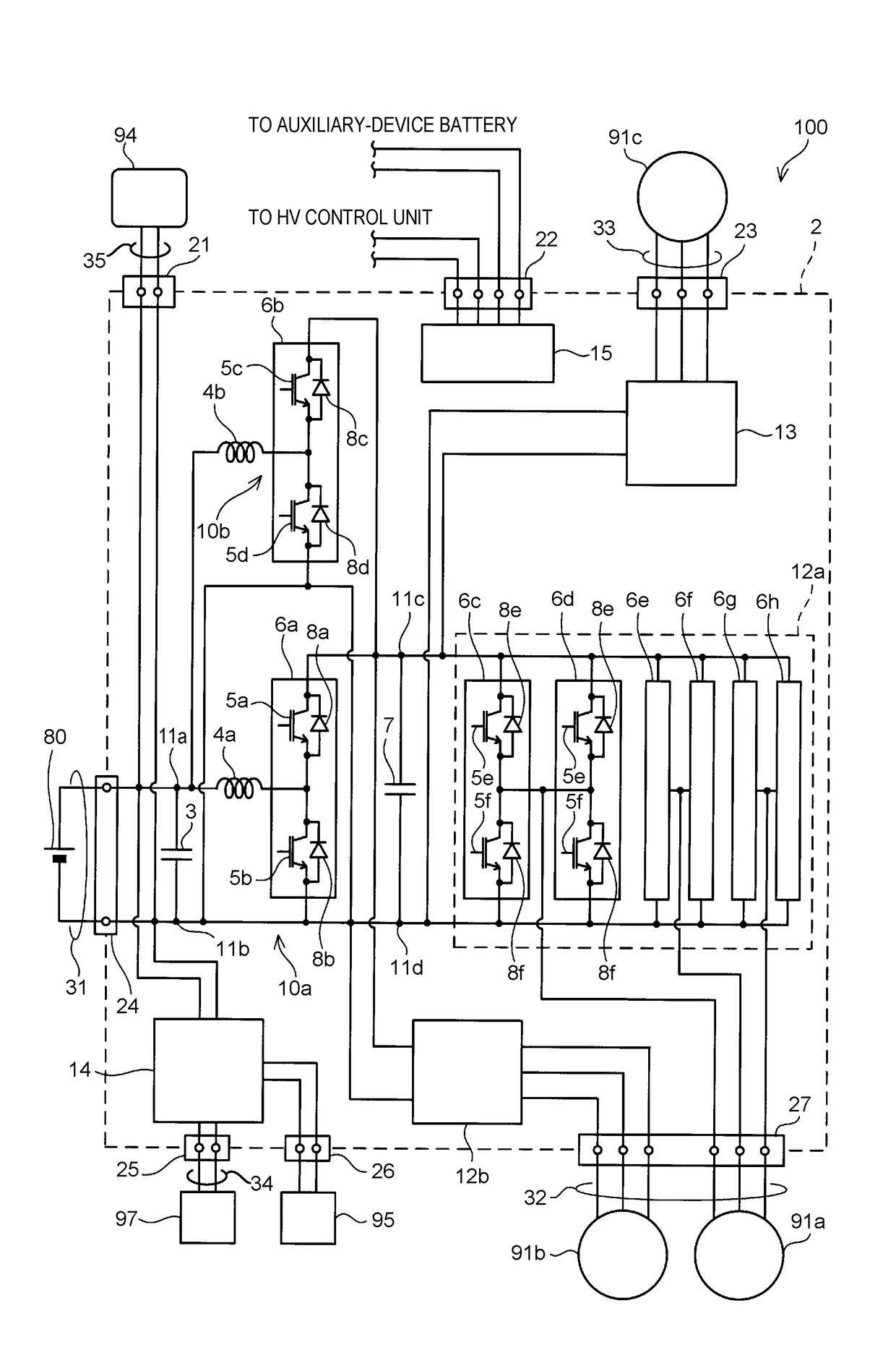
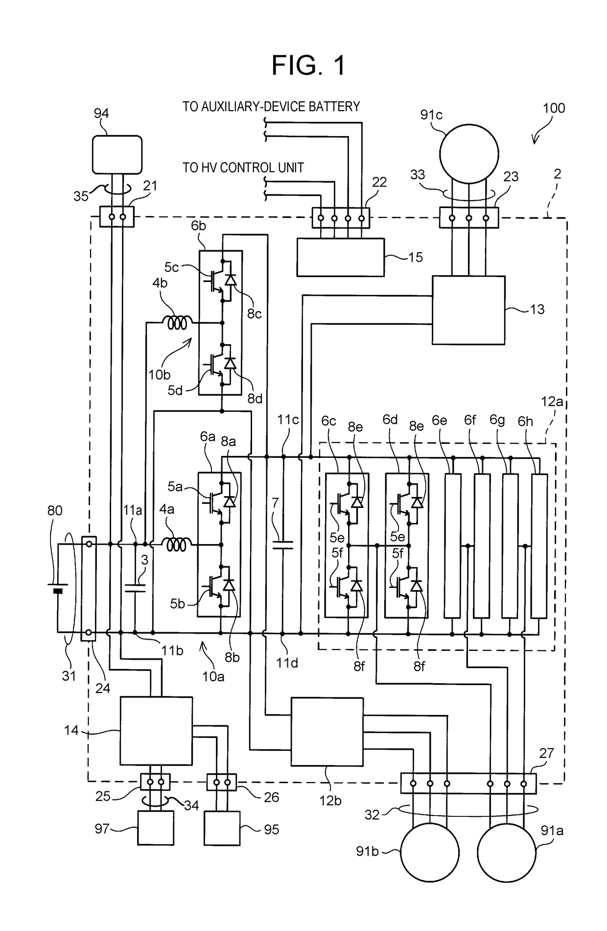
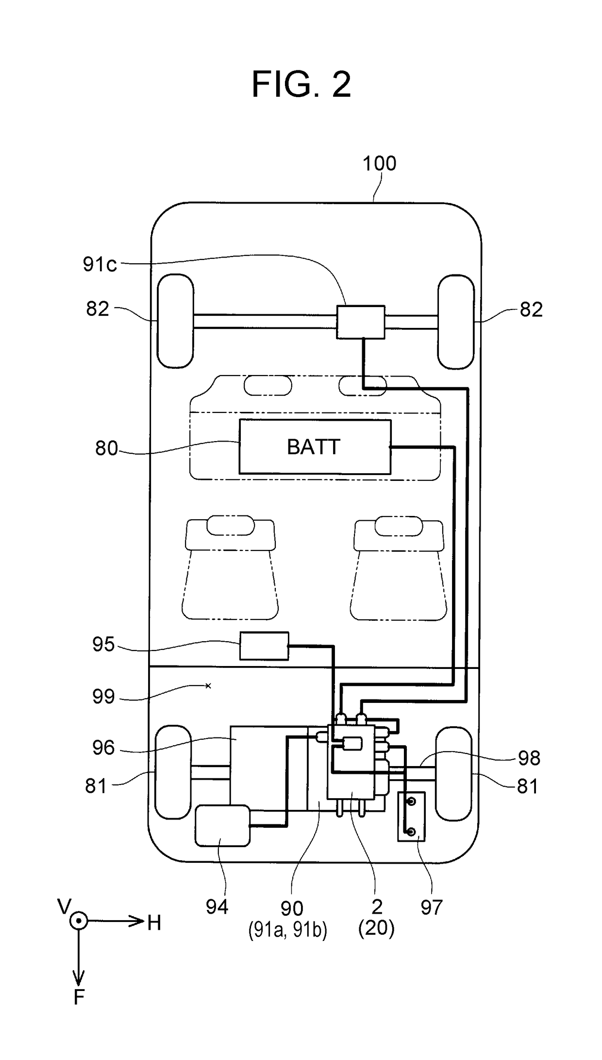
[0023]With reference to drawings, an electric automobile of an embodiment will be described. The electric automobile of the embodiment is a hybrid vehicle includes an engine and three motors as drive sources for traveling. First, an electric power system of a hybrid vehicle 100 will be described. FIG. 1 shows a block diagram of an electric power system of the hybrid vehicle 100. The hybrid vehicle 100 includes two motors (a first front motor 91a, a second front motor 91b) driving front wheels, and a rear motor 91c driving rear wheels. Hereinafter, for simplifying description, the first front motor 91a is referred to as a first F motor 91a, and the second front motor 91b is referred to as a second F motor 91b. Further, when the front motors and the rear motor are mentioned without being distinguished from each other, they are referred to simply as motors 91. Note that an electric automobile or a hybrid vehicle is one example of a vehicle in the present disclosure.

[0024]The three moto...


PUM


Abstract

A vehicle includes a motor housing accommodating motors for driving wheels, and a power control unit fixed on the motor housing. The power control unit includes: a stacked unit in which multiple power modules accommodating power semiconductor elements for electric power conversion and multiple coolers are stacked; and reactors. The stacked unit is disposed in the case of the power control unit such that the stacking direction of the power modules and the coolers is directed toward the vehicle-longitudinal direction. The reactors are disposed in the case so as not to overlap with the stacked unit as viewed from the stacking direction.

Description

INCORPORATION BY REFERENCE[0001]The disclosure of Japanese Patent Application No. 2017-067515 filed on Mar. 30, 2017 including the specification, drawings and abstract is incorporated herein by reference in its entirety.BACKGROUND1. Technical Field[0002]A technique disclosed in the present specification relates to a vehicle. In particular, the technique relates to a vehicle equipped with motors for driving wheels.2. Description of Related Art[0003]A vehicle equipped with motors for driving wheels includes a power control unit using electric power of an electric power source so as to control drive electric power of the motors. Hereinafter, a vehicle including motors for driving wheels is referred to as an electric automobile in some cases, and the motors for driving wheels are referred to simply as “motors” in some cases. In electric automobiles, power control units are fixed on motor housings so as to shorten power cables to supply electric power to the motors in some cases (Japanes...

Claims


Application Information

Patent Timeline
IPC IPC(8): B60L11/18B60K6/26B60K6/52B60K6/442B60L1/00H01L23/40H01L23/473
CPCB60L11/1803B60K6/26B60K6/52B60K6/442B60L1/00H01L23/4012H01L23/473B60K6/405B60L2210/14B60L2210/42B60R16/02H02P5/00H02P27/06B60L15/007H02M3/1584H02M7/003H02M7/5387H05K7/20927B60L2210/40B60L2240/525B60L50/51Y02T90/14Y02T10/7072H02M1/007H02M3/003H05K7/14329B60L53/20B60L53/16B60H1/00392B60L15/20B60Y2200/91B60Y2306/05B60K6/22H02M7/797H05K7/1432Y02T10/64Y02T10/70Y02T10/72
Inventor SAWAZAKI, KEISUKEYAMANAKA, KENSHIBABA, RYUSUKEYAMASAKI, HIROMIIMURA, HITOSHITACHIBANA, HIDEAKI
Owner TOYOTA JIDOSHA KK
Why Eureka
Try Eureka