Liquid crystal display and driving method thereof

Inactive Publication Date: 2009-07-02
LG DISPLAY CO LTD
View PDF18 Cites 12 Cited by
  • Summary
  • Abstract
  • Description
  • Claims
  • Application Information

AI Technical Summary

Benefits of technology

[0016]Another aspect of this document is to provide a liquid crystal display which reduces the length of a communication line for electrically connecting an

Problems solved by technology

When using the fluorescent lamps as the backlight, device characteristics of the LCD may be easily deteriorated due to the high power consumption and high heat generation of the fluorescent lamps.
In addition, the fluorescent lamps generally have a stick shape, so they do not withstand impacts well and can easily break on impact.
However, when the light emitting diodes are used as the backlight, since each light emitting diode is a semiconductor device, the lifetime of the LCD can be long, the lighting speed of the LCD can be fast, and the power consumption of the LCD can be low.
However, in the case that a package type illuminance sensor is mounted in a PCB as seen in FIG. 1, it is necessary to provide much additional space for the mounting area of the illuminance se

Method used


Image

  • Liquid crystal display and driving method thereof
  • Liquid crystal display and driving method thereof
  • Liquid crystal display and driving method thereof

Examples


Example

[0038]FIG. 3 is a plane view of a liquid crystal display in accordance with a first embodiment of the present invention. FIG. 4 is a perspective view of an example of a portion of the liquid crystal display of FIG. 3 in accordance with the first embodiment of the present invention.

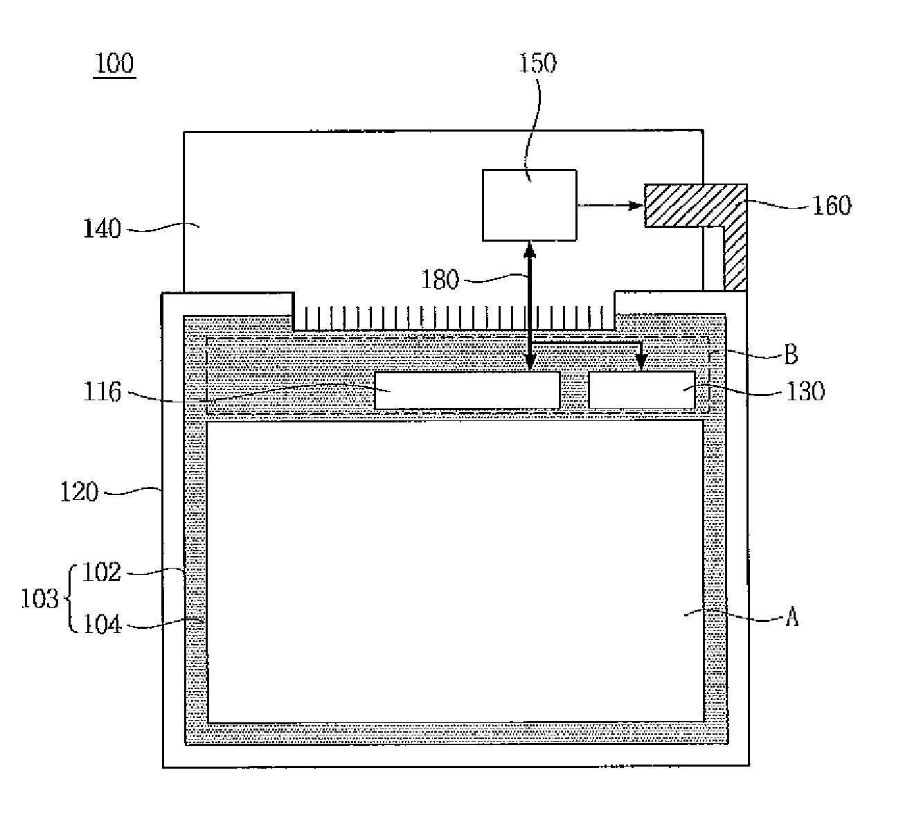
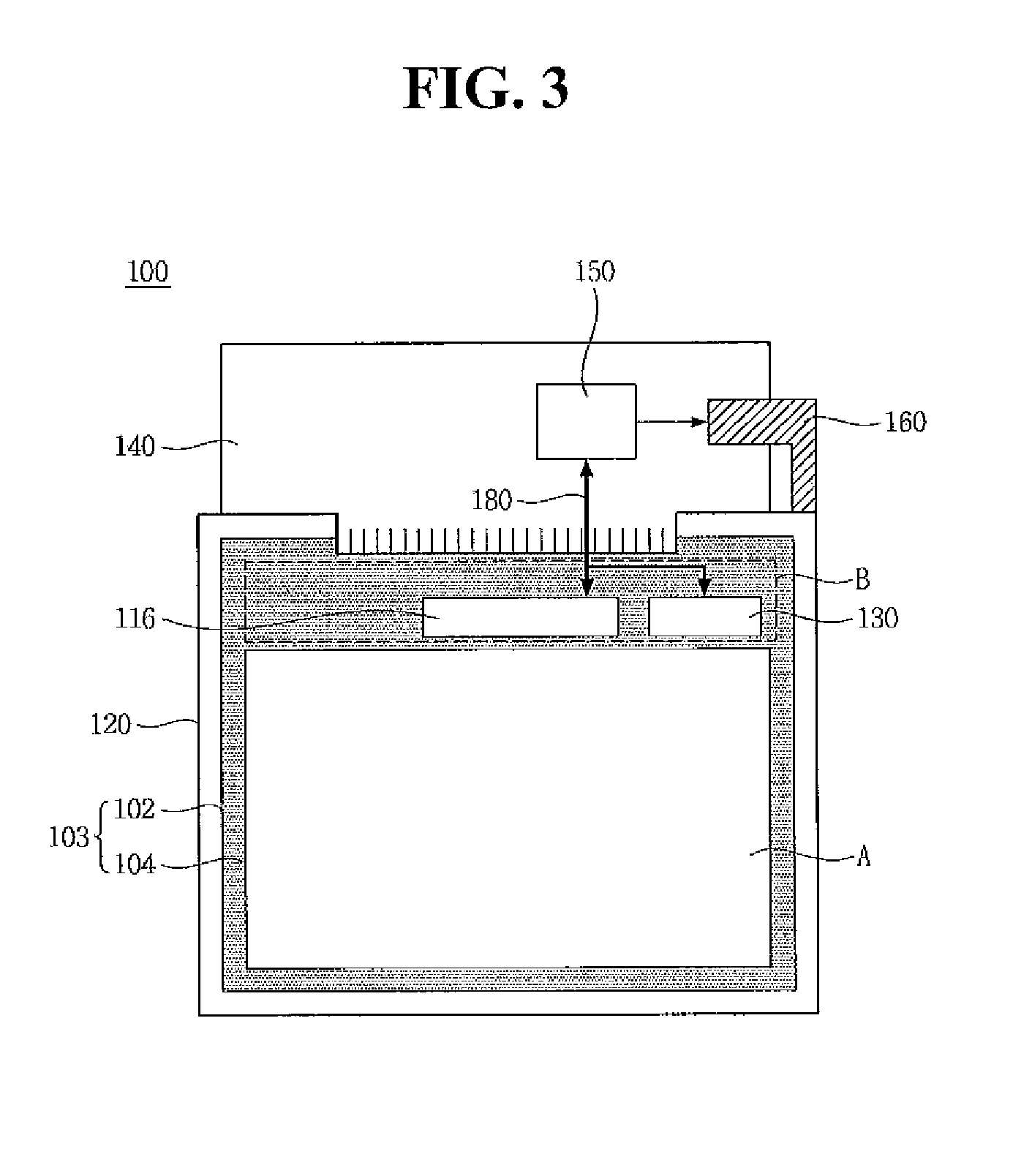
[0039]Referring to FIGS. 3 and 4, a liquid crystal display 100 in accordance with the first embodiment of the present invention includes a liquid crystal panel 103, a backlight unit 120 for radiating light on the liquid crystal panel 103, an illuminance sensor 130 mounted on the liquid crystal panel 103 to sense external light, a driving IC 116 for adjusting gamma characteristic(s) of data to be displayed on the liquid crystal panel 103 based on sensing information from the illuminance sensor 130, a PCB 170 arranged on the back surface of the liquid crystal panel 103 to generate a drive signal for driving the liquid crystal panel 103, a flexible printed circuit (hereinafter, “FPC”) for electrically connect...

Example

[0051]FIG. 5 is a plane view of a liquid crystal display in accordance with a second embodiment of the present invention. FIG. 6 is a perspective view of an example of a portion of the liquid crystal display of FIG. 5 in accordance with the second embodiment of the present invention.

[0052]Referring to FIGS. 5 and 6, the liquid crystal display 100 in accordance with the second embodiment of the present invention can include a liquid crystal panel 203, a backlight unit 220 for radiating light on the liquid crystal panel 203, an illuminance sensor 230 mounted on the liquid crystal panel 203 to sense external light, a driving IC 216 for adjusting gamma characteristic(s) of data to be displayed on the liquid crystal panel 203 based on sensing information from the illuminance sensor 230, a PCB 270 arranged on the back surface of the liquid crystal panel 203 to generate a drive signal for driving the liquid crystal panel 203, a FPC 240 for electrically connecting the PCB 270 to the driving...

Example

[0063]FIG. 7 is a plane view of a liquid crystal display in accordance with a third embodiment of the present invention.

[0064]Referring to FIG. 7, the liquid crystal display 300 in accordance with the third embodiment of the present invention is substantially the same as the liquid crystal display 200 in accordance with the second embodiment, except for the shape of a FPC 340 and the mounting method and mounting position of an illuminance sensor 330. Thus, the other components are given the same reference numerals as those of the liquid crystal display 200 in accordance with the second embodiment, and a detailed description thereof will be omitted. The third embodiment may substitute for the second embodiment in the case that, in the second embodiment, the width of the region, other than the region where the driving IC 216 is mounted, of the non-display region B is too small to mount the illuminance sensor 330 thereon, or the height of the illuminance sensor 330 to be mounted is rel...


PUM


Abstract

A liquid crystal display is disclosed with a reduced thickness. According to an embodiment, the liquid crystal display device includes a liquid crystal panel including upper and lower substrates and divided into an effective display region and a non-display region adjacent to the effective display region; a backlight unit configured to supply light to the effective display region; a backlight driving unit configured to control an operation of the backlight unit; a driving IC configured to control data to be displayed in the effective display region; an illuminance sensor configured to sense light external to the liquid crystal display device; and a flexible printed circuit (FPC) on which the backlight driving unit is disposed, the driving IC and the illuminance sensor being disposed adjacent to each other in the non-display region over the lower substrate.

Description

[0001]This application claims the benefit of Korea Patent Application No. 10-2007-0138304 field on Dec. 27, 2007, which is incorporated herein by reference for all purposes as if fully set forth herein.BACKGROUND[0002]1. Field[0003]This document relates to a liquid crystal display, and more particularly, to a liquid crystal display which can be made slim while incorporating an illuminance sensor.[0004]2. Related Art[0005]In general, the scope of application of liquid crystal displays has widened due to the lightweight, thinness, and low power consumption of liquid crystal displays. According to this trend, liquid crystal displays are widely used in office automation machines and audio / video machines. The intensity of light beam is adjusted in accordance with a video signal applied to a plurality of control switches arranged in a matrix in order to display a desired picture on a screen.[0006]Since such LCDs are non-emissive devices, the LCDs generally need a light unit such as a back...

Claims


Application Information

Patent Timeline
IPC IPC(8): G09G3/36G02F1/13357
CPCG02F1/13318G02F1/13452G02F2201/58G09G3/3406G09G2360/144G09G2320/0276G09G2320/0626G09G2330/021G09G3/3611G02F1/1345
Inventor PARK, JAEDEOKKWON, SANGHOON
Owner LG DISPLAY CO LTD
Why Eureka
Try Eureka