Toner supplier apparatus

a supplier and toner technology, applied in the direction of electrographic process apparatus, instruments, optics, etc., can solve the problems of lowering accuracy for controlling the concentration of toner, and achieve the effect of improving measurement accuracy, facilitating stable concentration control, and improving accuracy control

Active Publication Date: 2012-04-03
MIYAKOSHI PRINTING MACHINERY
View PDF11 Cites 1 Cited by
  • Summary
  • Abstract
  • Description
  • Claims
  • Application Information

AI Technical Summary

Benefits of technology

[0018]The toner supplier apparatus according to the present invention enabling more accurate control for the concentration of the toner using the concentration sensor than in a conventional case, thereby resulting in an improvement in the accuracy in measuring the concentration of the toner reserved in the main tank because the toner supplier apparatus is configured to control the concentration of the liquid toner (also simply called toner) reserved in the main tank by supplying the high concentration toner from the high-concentration-toner-supplier section to the main tank and by supplying the diluent from the diluent-supplier section to the main tank based on the concentration of the toner measured by the concentration sensor provided in the toner-feeding pipeway. This facilitates the stable control for the concentration of the toner reserved in the main tank more significantly than in a conventional case, and provides accurate control for the concentration in a printed image.
[0019]In addition, the temperature controller apparatus provided in the vicinity of the main tank can restrict an increase of the temperature of the toner and reduce the occurrence of error in the concentration measured by means of the concentration-measuring sensor using an ultrasonic wave.

Problems solved by technology

However, accuracy may be lowered for controlling the toner concentration since the concentration of the toner measured by the concentration sensor is vulnerable to the toner dispersed in the toner reservoir.

Method used


Image

  • Toner supplier apparatus
  • Toner supplier apparatus
  • Toner supplier apparatus

Examples


Embodiment Construction

[0024]An example of the toner supplier apparatus as an implementation of the present invention will be explained as follows with reference to drawings.

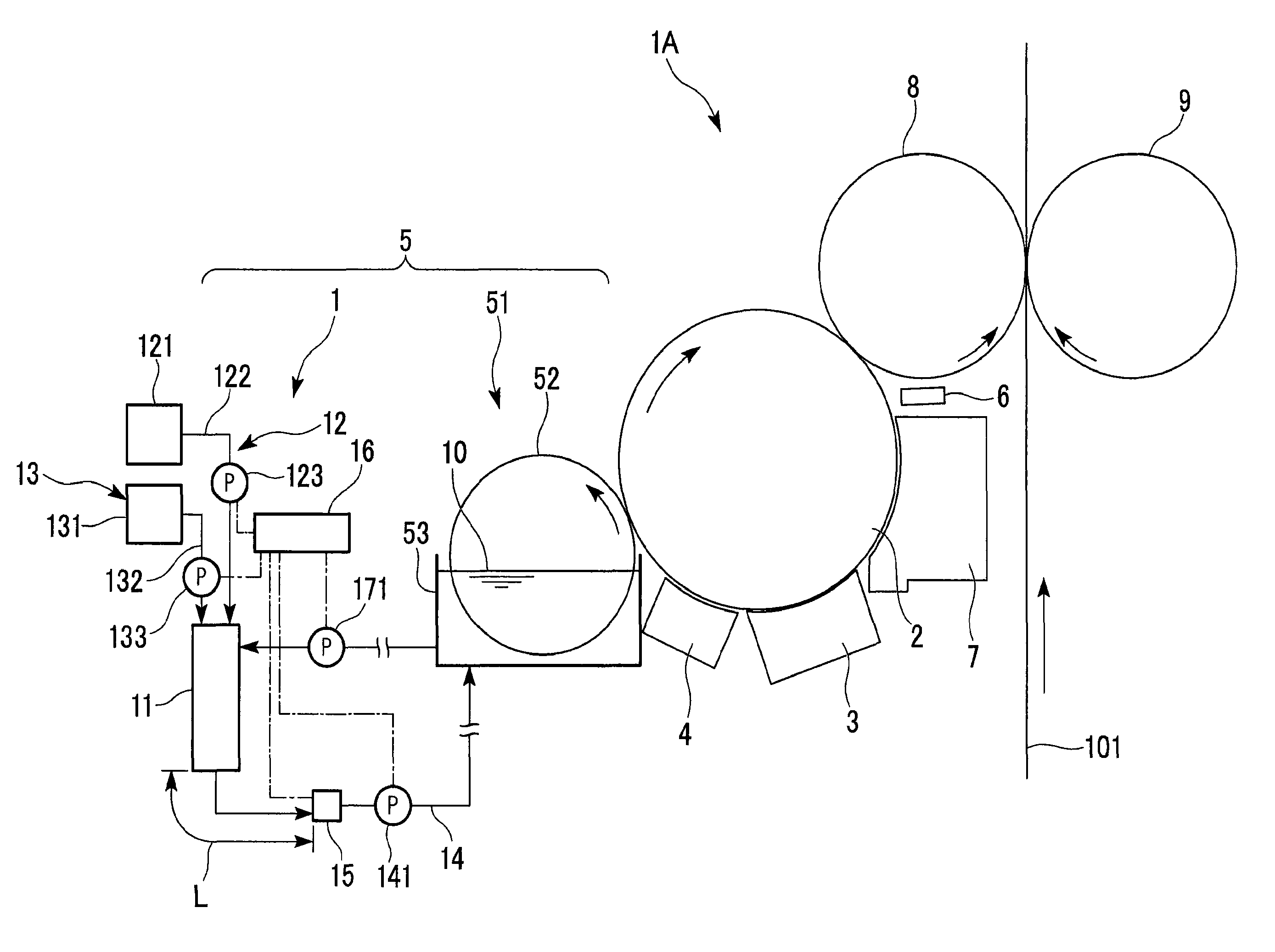
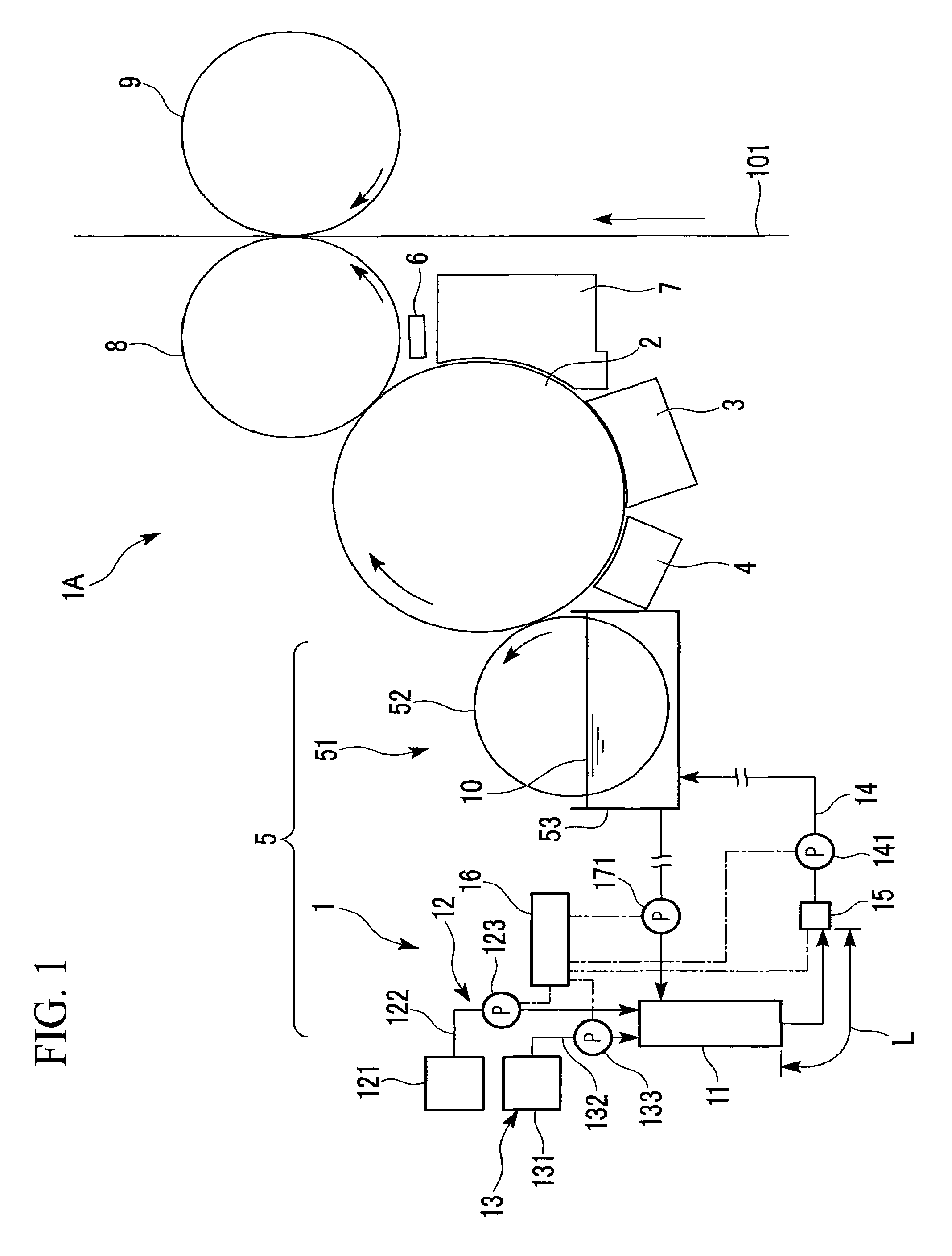
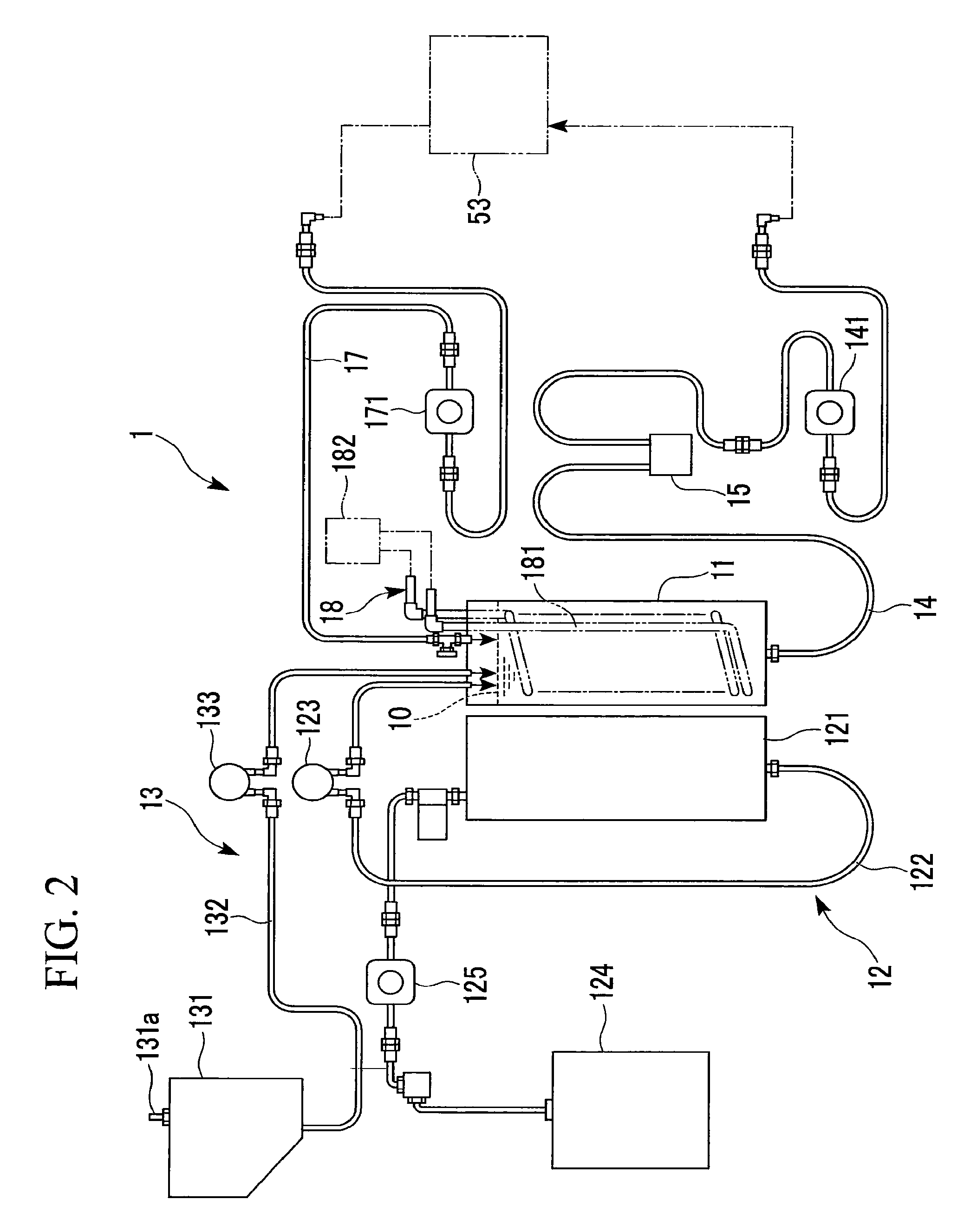
[0025]FIG. 1 is a front elevation showing the configuration of an electronic photograph printer 1A adopting a toner supplier apparatus 1 according to the present invention. FIG. 2 is a general view showing the configuration of the toner supplier apparatus 1. FIGS. 3A and 3B show an example of the structure of a concentration sensor adopted in the toner supplier apparatus 1.

[0026]FIG. 1 shows the configuration of the electronic photograph printer 1A including: a photosensitive drum 2; a static-charging apparatus 3; an exposure apparatus 4; a developer apparatus 5; a static-eliminating apparatus 6; a photosensitive-material cleaner 7; a transfer roll 8; and a backup roller 9. The toner supplier apparatus 1 is provided in the developer apparatus 5.

[0027]Reference numeral 101 in FIG. 1 indicates a recording paper. A swathe of the elongate...


PUM


Abstract

A toner supplier apparatus 1 is provided for stabilizing the concentration of toner reserved in a main tank. A concentration sensor for measuring the concentration of the toner is provided in a toner-feeding pipeway for supplying liquid toner from a main tank for adjusting the concentration to the developer apparatus. High concentration toner and diluent supplied to the main tank are controlled based on the concentration measured by the concentration sensor. Accordingly, accuracy of the toner supplier apparatus used for an electronic photograph printer in measuring the concentration of the toner can be improved, thereby permitting accurate control for the concentration in a printed image.

Description

[0001]The present application is based on patent application No. 2008-002375 filed in Japan on Jan. 9, 2008, the content of which is incorporated herein by reference.BACKGROUND OF THE INVENTION[0002]1. Field of the Invention[0003]The present invention relates to a toner supplier apparatus for supplying a liquid toner to a developer apparatus of a wet type electronic photograph printer using liquid toner.[0004]2. Description of the Related Art[0005]Maintaining the concentration of toner within a fixed range is extremely important in a wet-type electronic photograph printer using liquid toner (hereinafter simply called toner) since the concentration of a printed image depends on the concentration of the toner. A solution proposed in view of this situation is a toner-adjusting apparatus for adjusting the concentration of toner for image development (see for example, Patent Document 1)[0006]The Patent Document 1 discloses a toner-adjusting apparatus including: a toner reservoir for adju...

Claims


Application Information

Patent Timeline
Patent Type & Authority Patents(United States)
IPC IPC(8): G03G15/10
CPCG03G15/553G03G15/556
Inventor IZAWA, HIDEOMERA, SUMITOHARADA, KOTAROKOMATSUDA, SEIJI
Owner MIYAKOSHI PRINTING MACHINERY
Why Eureka
Try Eureka