Unlock instant, AI-driven research and patent intelligence for your innovation.

Cable assembly with improved termination disposition

Inactive Publication Date: 2010-01-26
HON HAI PRECISION IND CO LTD
View PDF7 Cites 68 Cited by
  • Summary
  • Abstract
  • Description
  • Claims
  • Application Information

AI Technical Summary

Benefits of technology

[0005]Accordingly, an object of the present invention is to prov

Problems solved by technology

However, such arrangement of the terminal dispositions not only increases dimension of an

Method used


Image

  • Cable assembly with improved termination disposition
  • Cable assembly with improved termination disposition
  • Cable assembly with improved termination disposition

Examples


Embodiment Construction

[0016]Reference will now be made in detail to the preferred embodiment of the present invention.

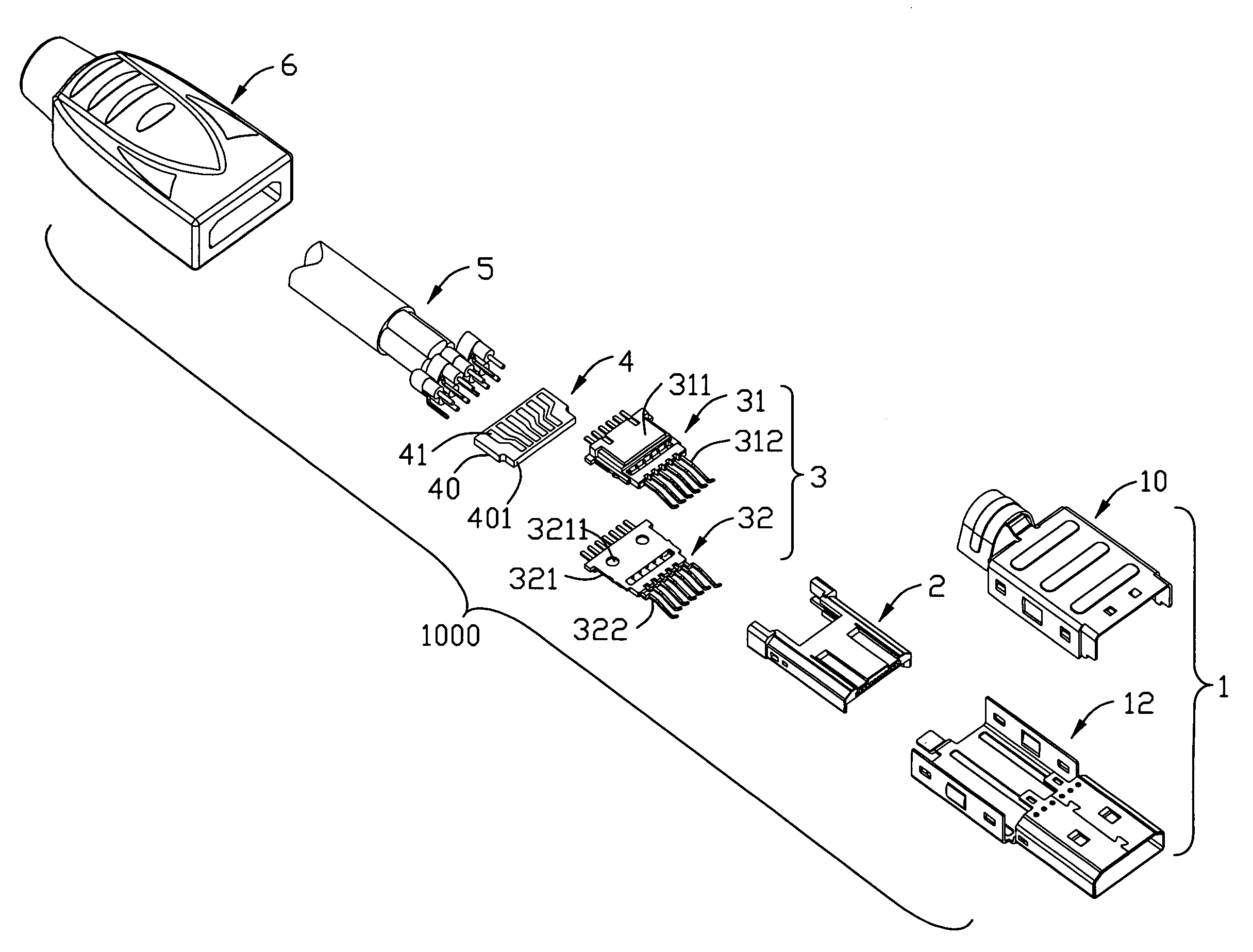
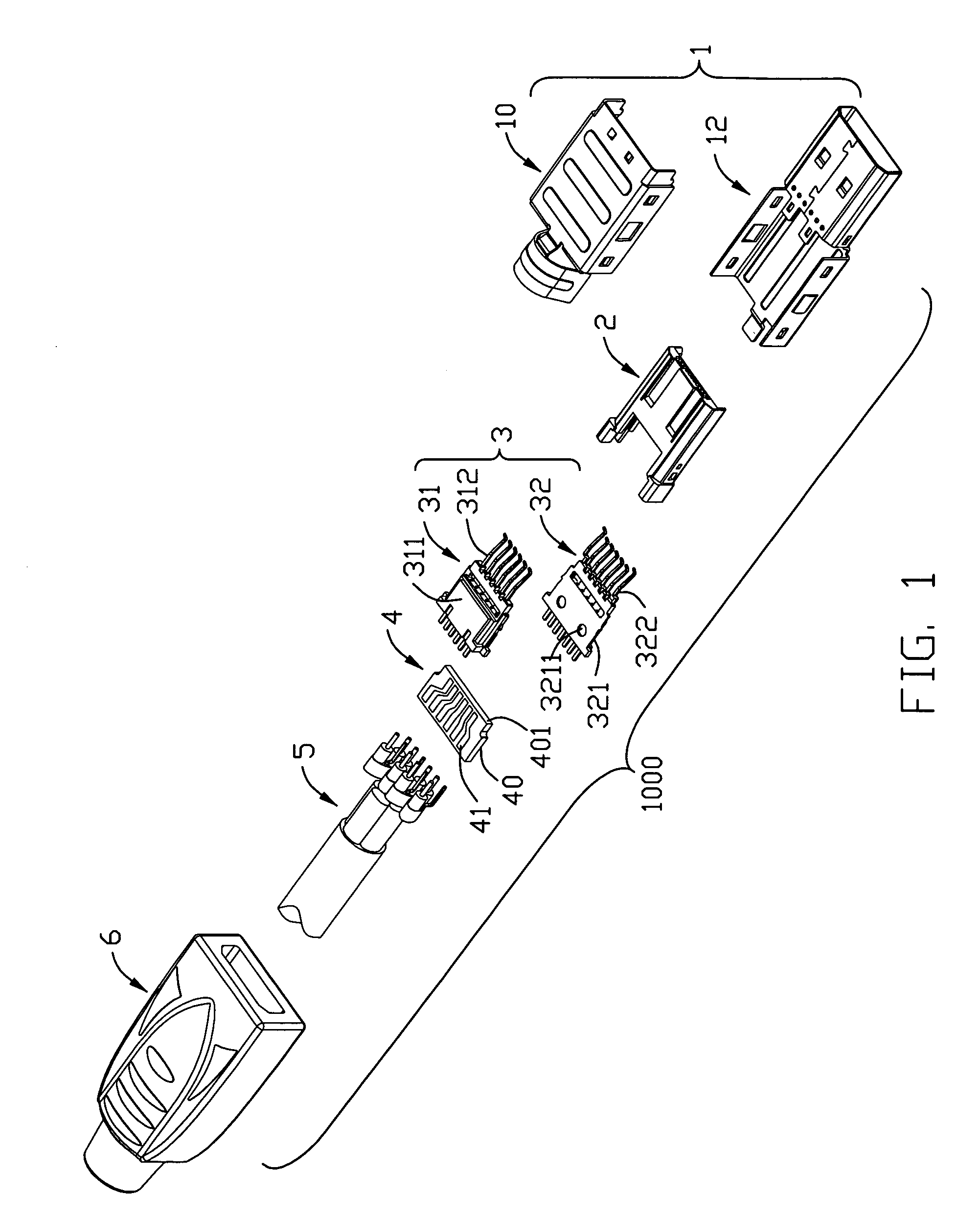
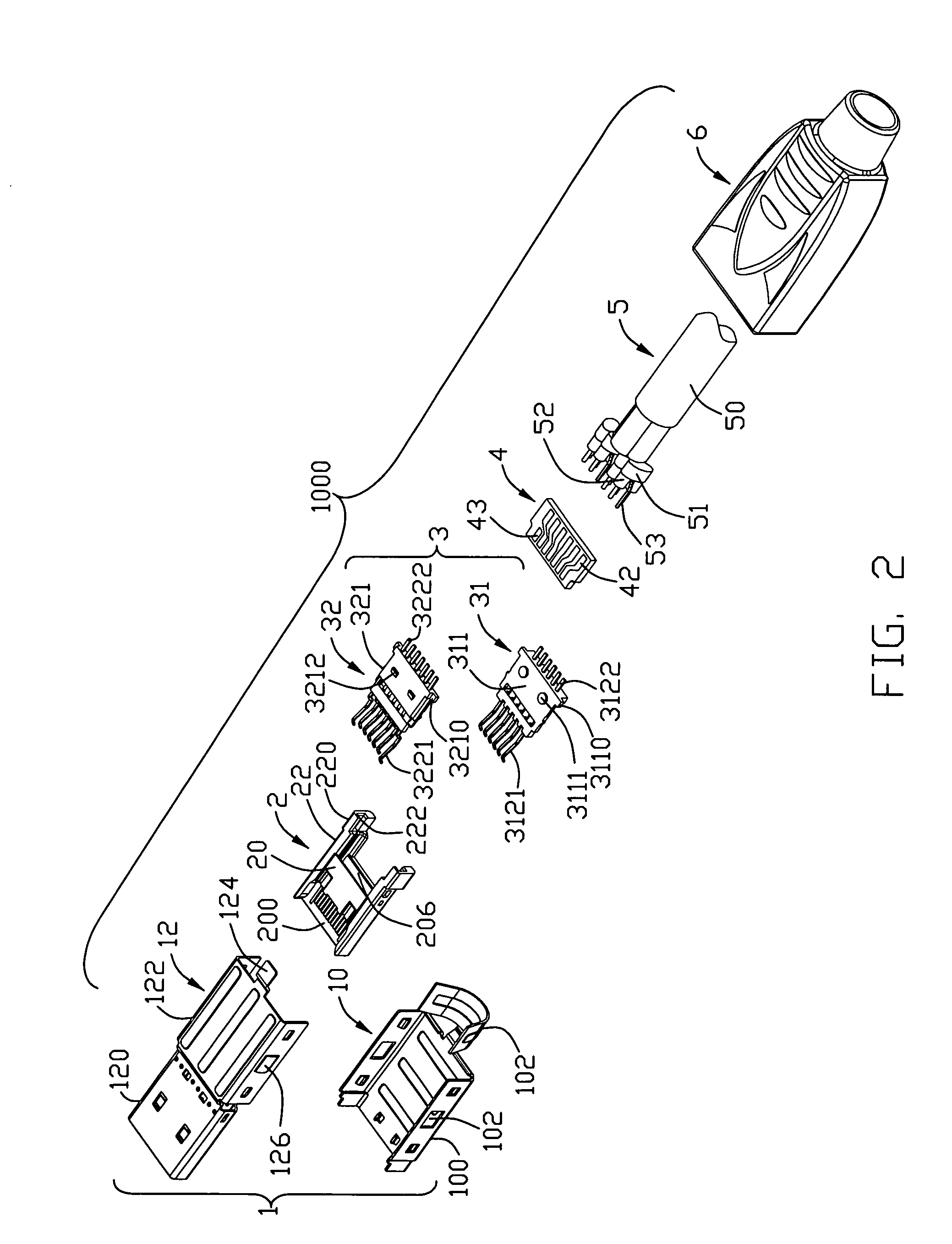
[0017]Referring to FIGS. 1-7, a cable assembly 1000 comprises a metallic shell 1, an insulated housing 2, a contact module 3, a printed circuit board (PCB) 4, a cable 5 and an insulated cover 6.

[0018]The metallic shell 1 includes a first shielding member 10 and a second shielding member 12. The first shielding member 10 has an inverted U-shaped first shielding portion 100 and a cable holder portion 102 coupled to a back edge of an upper side of the first shielding portion 10. The second shielding member 12 has a rectangular-shaped sleeve portion 120 and a U-shaped second shielding portion 122 extending rearward from back edge of a bottom side of the sleeve portion 120. A tab 124 is formed at rear edge of a bottom side of the second shielding portion 122. The first shielding member 10 latches with the second shielding member 12, with protrusions 126 formed on lateral sides of the second sh...


PUM


Abstract

A cable assembly includes an insulated housing defining a cavity portion along a longitudinal direction; a first contact module including a first insulator combined with a plurality of first contacts, each of the first contacts having a mating portion extending beyond a front surface of the first insulator and a tail portion disposed outside a back surface of the first insulator; a second contact module including a second insulator combined with a plurality of second contacts, each of the second contacts having a mating portion extending beyond a front surface of the second insulator and a tail portion disposed outside a back surface of the second insulator;
the first insulator overlapped with the second insulator, with each of the mating portions of the first contacts disposed into a corresponding gap between two adjacent mating portions of the second contacts, and the tail portions of first contacts spaced apart the tail portions of second contacts; and the first and second contact module inserted into the cavity portion of the insulated housing, with the mating portions of the first contacts and the second contacts extending into a mating port of the insulated housing, and the tail portions of the first and second contacts disposed outside of the cavity portion of the insulated housing and adapted for soldering to wires.

Description

FIELD OF THE INVENTION[0001]The present invention generally relates to a cable assembly, and more particularly to a cable assembly having an improved termination disposition.DESCRIPTION OF PRIOR ART[0002]Many electronic devices rely upon transmission lines to transmit signals between related devices or between peripheral devices and circuit boards of a computer. These transmission lines incorporate signal cables that are capable of high-speed data transmissions.[0003]These signal cables may use what are known as one or more twisted pairs of wires that are twisted together along the length of the cable, with each such twisted pair being encircled by an associated grounding shield. These twisted pairs typically receive complementary signal voltages, i.e., one wire of the pair may see a +1.0 volt signal, while the other wire of the pair may see a −1.0 volt signal. Thus, these wires may be called “differential” pairs, a term that refers to the different signals they carry. At present, H...

Claims


Application Information

Patent Timeline
IPC IPC(8): H01R9/00
CPCH01R12/62H01R13/514H01R13/6658H01R9/034H01R13/65914
Inventor WU, JERRY
Owner HON HAI PRECISION IND CO LTD