Stent-graft with anchoring pins

a technology of anchoring pins and stents, which is applied in the field of deploying stents, can solve the problems of repositioning the stent, down retraction, and room for error in placement, and achieves the effect of avoiding retraction, avoiding retraction, and avoiding retraction

Active Publication Date: 2010-02-02
MEDTRONIC VASCULAR INC
View PDF43 Cites 267 Cited by
  • Summary
  • Abstract
  • Description
  • Claims
  • Application Information

AI Technical Summary

Benefits of technology

[0016]A method of deploying the endoprosthesis includes radially constraining the proximal anchor stent ring of the endoprosthesis in an annular space between the sleeve of the tapered tip and the spindle. The method further includes radially constraining a graft material of the endoprosthesis in a primary sheath, the graft material being attached to a distal end of the proximal anchor stent ring. By radially constraining the graft material of the endoprosthesis by the primary sheath and radially constraining the proximal anchor stent ring by the sleeve, sequential and independent deployment of the graft material and the proximal anchor stent ring is facilitated.
[0018]Further, as the proximal end of the endoprosthesis is secured and, in one example, the distal end is free to move within the primary sheath, bunching of the endoprosthesis during retraction of the primary sheath is avoided. By avoiding bunching, frictional drag of the endoprosthesis on the primary sheath during retraction is minimized thus facilitating smooth and easy retraction of the primary sheath.

Problems solved by technology

Such a configuration leaves little room for error in placement since re-positioning the stent-graft after initial deployment, except for a minimal pull down retraction, is usually difficult if possible at all.
Attempts to overcome this problem generally fail to provide adequate control in manipulating the stent-graft positioning in both the initial deployment of the stent-graft and the re-deployment of the stent-graft (once the stent-graft has been partially deployed).
Another problem encountered with existing systems, particularly with systems that have a distal end of a stent-graft fixed during deployment (or during the uncovering of the sheath) is the frictional forces that can cause the stent-graft to axially compress or bunch up as the sheath is retracted.
This bunching increases the density of the stent-graft within the sheath and can further increase the frictional drag experienced during deployment.

Method used


Image

  • Stent-graft with anchoring pins
  • Stent-graft with anchoring pins
  • Stent-graft with anchoring pins

Examples


Embodiment Construction

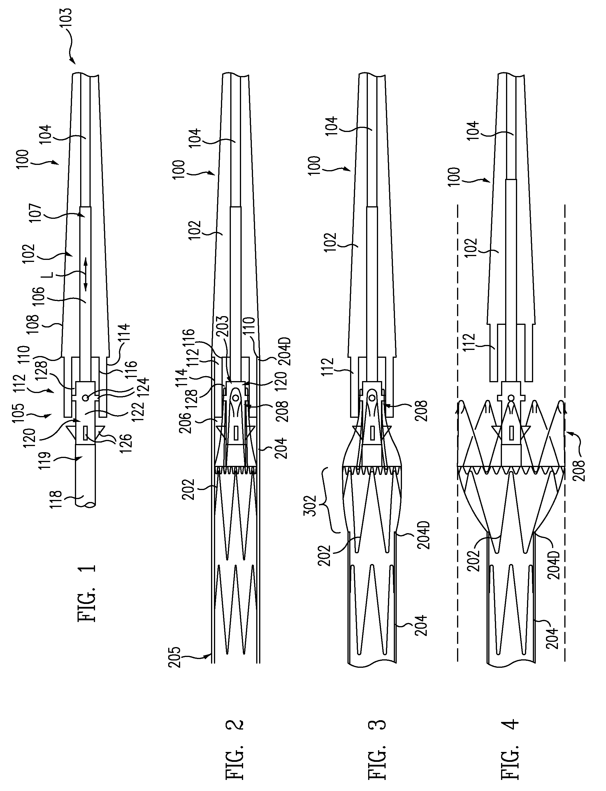
[0042]FIG. 1 is a partial cross-sectional view of a stent-graft delivery system 100 without a stent-graft and outer sheath in accordance with one embodiment. Stent-graft delivery system 100 includes a tapered tip 102 that is flexible and able to provide trackability in tight and tortuous vessels. Tapered tip 102 includes a guidewire lumen 104 therein for connecting to adjacent members and allowing passage of a guidewire through tapered tip 102. Other tip shapes such as bullet-shaped tips could also be used.

[0043]An inner tube 106 defines a lumen, e.g., a guide wire lumen, therein. A distal end 107 of inner tube 106 is located within and secured to tapered tip 102, i.e., tapered tip 102 is mounted on inner tube 106. As shown in FIG. 1, the lumen of inner tube 106 is in fluid communication with guidewire lumen 104 of tapered tip 102 such that a guide wire can be passed through inner tube 106 and out distal end 107, through guidewire lumen 104 of tapered tip 102, and out a distal end 1...


PUM


Abstract

A proximal anchor stent ring of an endoprosthesis includes proximal apexes, distal apexes, struts extending between the proximal apexes and the distal apexes, and anchor pins. The struts, the proximal apexes, and the distal apexes define an imaginary cylindrical surface. A pair of the anchor pins is located on the struts adjacent each of the proximal apexes, the anchor pins extending inwards from inside surfaces of the struts and protruding from the struts radially outward from the cylindrical surface. By locating the anchor pins inwards, the delivery profile of the proximal anchor stent ring is minimized.

Description

BACKGROUND OF THE INVENTION[0001]1. Field of the Invention[0002]This invention relates generally to medical devices and procedures, and more particularly to a method and system of deploying a stent-graft in a vascular system and to the associated stent-graft.[0003]2. Description of the Related Art[0004]Prostheses for implantation in blood vessels or other similar organs of the living body are, in general, well known in the medical art. For example, prosthetic vascular grafts formed of biocompatible materials (e.g., Dacron or expanded, porous polytetrafluoroethylene (PTFE) tubing) have been employed to replace or bypass damaged or occluded natural blood vessels.[0005]A graft material supported by a framework is known as a stent-graft or endoluminal graft. In general, the use of stent-grafts for treatment or isolation of vascular aneurysms and vessel walls which have been thinned or thickened by disease (endoluminal repair or exclusion) is well known.[0006]Many stent-grafts, are “self...

Claims


Application Information

Patent Timeline
Patent Type & Authority Patents(United States)
IPC IPC(8): A61F2/06
CPCA61F2/07A61F2/95A61F2002/8483A61F2230/0054A61F2002/9505A61F2/89A61F2002/075A61F2002/8486
Inventor MITCHELL, JAMESRUST, MATTHEWGREENAN, TREVORYANG, FRANK
Owner MEDTRONIC VASCULAR INC
Why Eureka
Try Eureka