Voltage shifter circuit

a voltage shifter and circuit technology, applied in logic circuits, logic circuit coupling/interface arrangements, pulse techniques, etc., can solve the problems of difficult optimization of the duty cycle of the output voltage, slow voltage shift speed, and increased paralytic capacitance, and achieve the effect of wide operation voltage range and high speed

Active Publication Date: 2010-02-23
SEMICON MFG INT (SHANGHAI) CORP
View PDF3 Cites 1 Cited by
  • Summary
  • Abstract
  • Description
  • Claims
  • Application Information

AI Technical Summary

Benefits of technology

[0009]An object of the present invention is to provide a voltage shifter circuit with a wide operation voltage range and a high speed.
[0022]Compared with the prior art, the present invention has the following advantages. The competition between the pull-up circuit and the pull-down circuit is avoided since the control circuit is used to control the pull-up circuit. Therefore, the speed of the voltage shifter circuit is improved and the voltage shifter circuit can operate within a wider voltage range (i.e. the large difference between the first voltage and the high voltage of the signal from the input signal source is allowed). The delay time of the pull-up circuit and the pull-down circuit is small and the duty cycle is small. Hence, the present invention may be applied to the circuit of 90 nm-below technology with a high speed and a small delay. In addition, since no direct current path is established, no current is wasted.
[0023]Additionally, the above solution further optimizes the duty cycle by using the second delayer to avoid the delay time between the pull-up circuit and the pull-down circuit.

Problems solved by technology

However, the parasitic capacitance is increased and the voltage shifting speed is lowed.
In addition, the duty cycle of the output voltage is difficult to be optimized due the competition between the pull-up circuit and the pull-down circuit.
However, the problems can not be solved completely.
Especially when the difference between the voltage for the core circuit region and the voltage for the I / O circuit region is large, the speed is further affected.
In addition, since the competition between the pull-up circuit 100 and the pull-down circuit 200 still exists, the device is sensitive to the process and the duty cycle is difficult to be controlled.
Moreover, a direct current path exists from the first voltage source V2 (about 3.3V) to the ground terminal during the voltage shifting, and the power efficiency is lowed.

Method used


Image

  • Voltage shifter circuit
  • Voltage shifter circuit
  • Voltage shifter circuit

Examples


Embodiment Construction

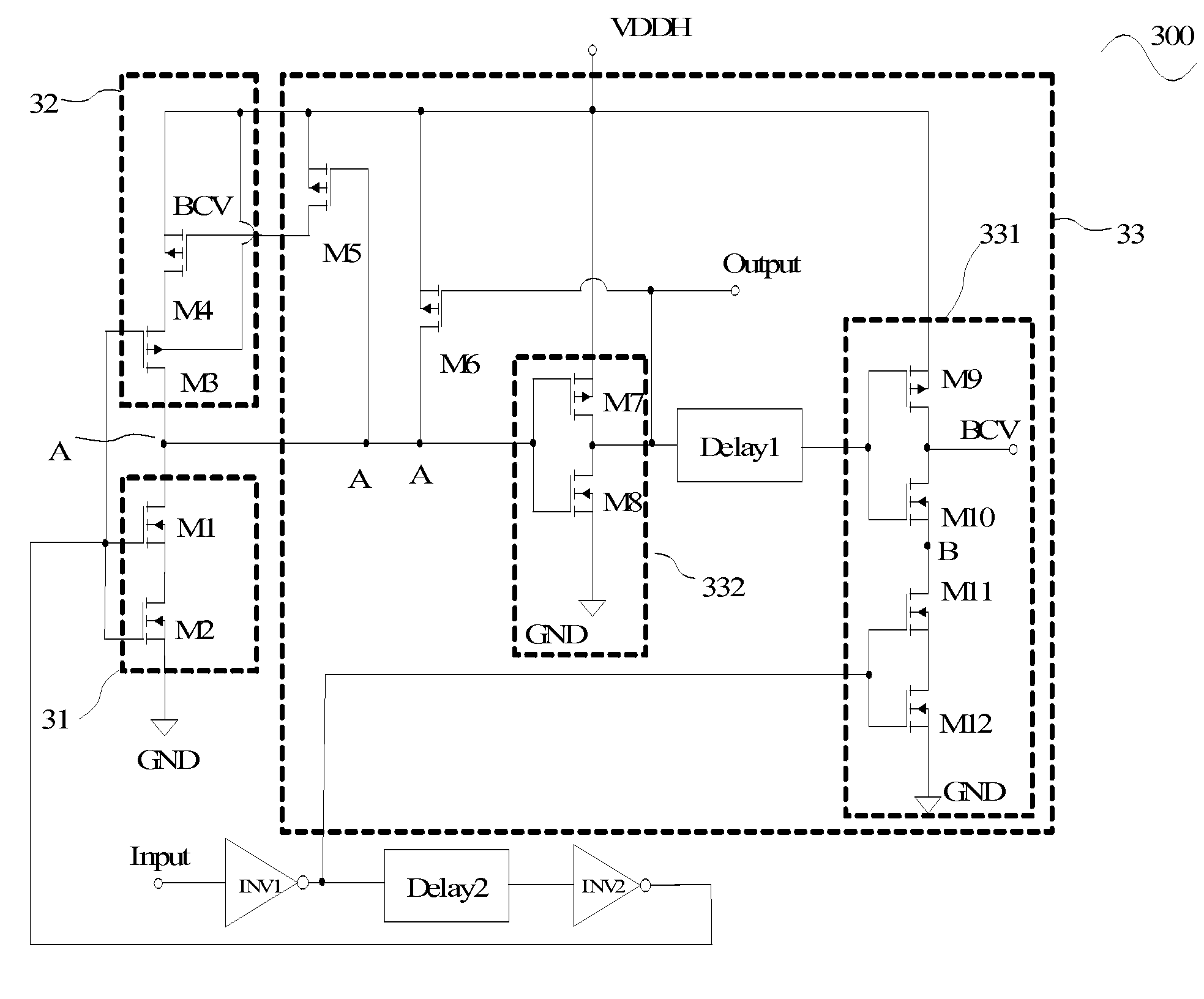
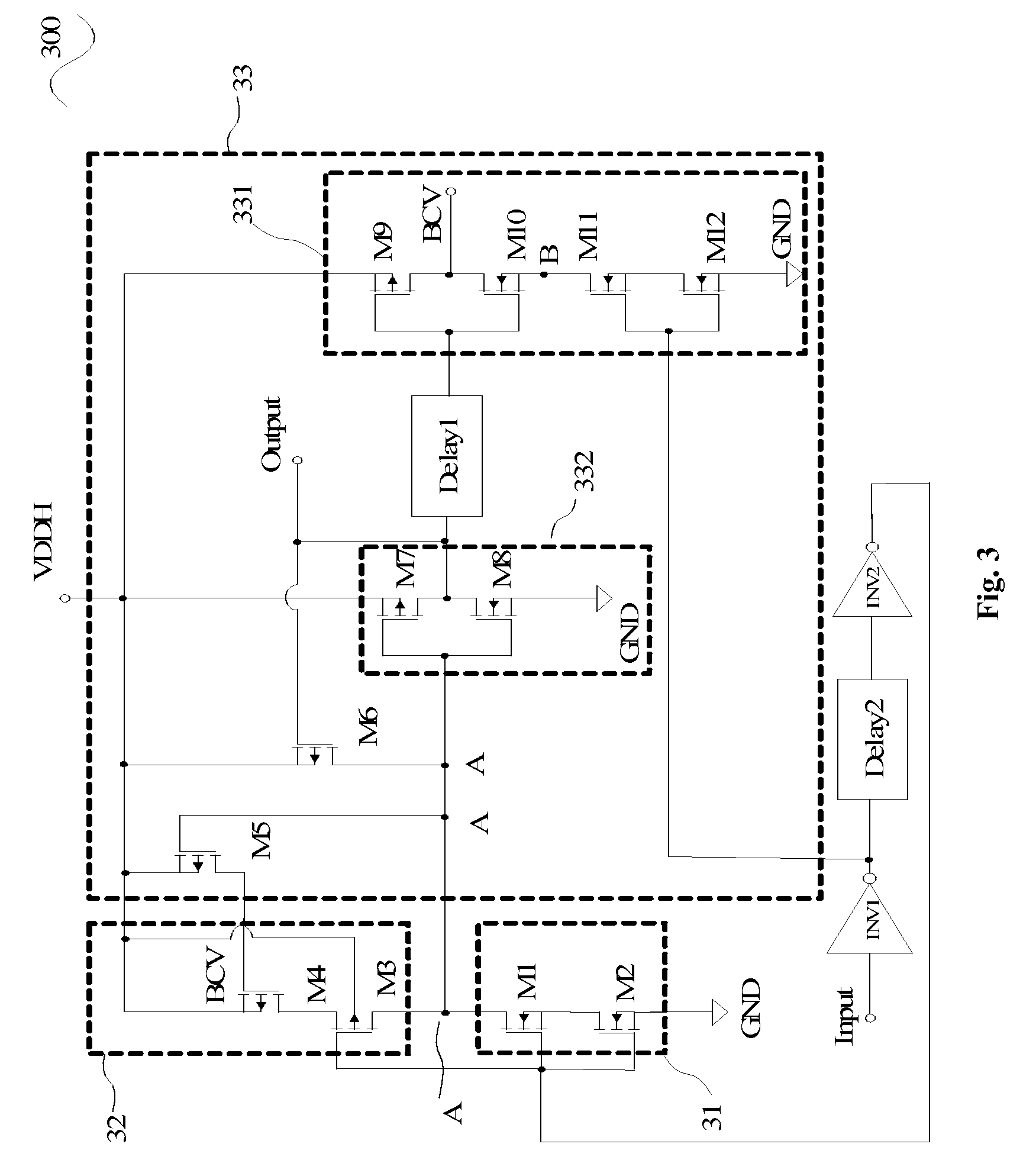
[0030]The present invention provides a voltage shifter circuit in which a control circuit is used to control a pull-up circuit, so that the pull-up circuit is turned off when an input signal changes from a low voltage to a high voltage. Therefore, the competition between the pull-up circuit and the pull-down circuit will not be caused.

[0031]First of all, one embodiment of the present invention provides a voltage shifter circuit, including: a pull-up circuit, connected to a first voltage source; a pull-down circuit, located between the pull-up circuit and a ground terminal and connected to an input signal source, adapted to make the voltage shifter circuit output a modulated pulse signal having a high voltage of the first voltage and a low voltage of zero with an operation together with the pull-down circuit; a node, at which the pull-up circuit and the pull-down circuit are connected; and the voltage shifter circuit further includes a control circuit, including: a second inverter, o...


PUM


Abstract

The present invention provides a voltage shifter circuit, in which a control circuit is used to control the pull-up circuit, so that the pull-up circuit is kept as off when the signal from the input signal source changes from a low voltage to a high voltage. Hence, the competition between the pull-up circuit and the pull-down circuit is avoided. The speed of the voltage shifter circuit is improved and the voltage shifter circuit can operate within a wider voltage range. The delay time of the pull-up circuit and the pull-down circuit is small and the duty cycle is small. In addition, since no direct current path is established, no current is wasted. Additionally, the voltage shifter circuit uses the second delayer to compensate the delay time between the pull-up circuit and the pull-down circuit and optimizes the duty cycle.

Description

[0001]The present application claims the benefit of Chinese Application No. 200710041094.7 filed on May 23, 2007, titled “VOLTAGE SHIFTER CIRCUIT”, which is incorporated herein by reference in its entirety.FIELD OF THE INVENTION[0002]The present invention relates to a voltage shifter circuit.BACKGROUND OF THE INVENTION[0003]In modern Integrated Circuit (IC) system, the core logic unit is designed to operate with 1.0V (with the 65 nm technology) to obtain a high speed, while the Input / Output (I / O) unit is designed to operate with 3.3V, 2.5V or 1.8V to realize the stabilization. Due to the different operation voltages, a converting circuit is configured between the core logic unit and the I / O unit, so that the voltage of 1.0V can be converted into the voltage of 3.3V. The above converting circuit is also referred as a voltage shifter circuit.[0004]FIG. 1 shows a voltage shifter circuit 10 in the prior art, including: PMOS transistors PG1 and PG2; NMOS transistors NG1 and NG2; and an i...

Claims


Application Information

Patent Timeline
Patent Type & Authority Patents(United States)
IPC IPC(8): H03K19/0175
CPCH03K19/018528
Inventor FU, ZHIGANGLIN, CHING LONG
Owner SEMICON MFG INT (SHANGHAI) CORP
Why Eureka
Try Eureka