Adjustable steering apparatus

a steering apparatus and adjustment technology, applied in the direction of steering column, steering components, vehicle components, etc., can solve the problems of airbags being deployed in improper positions, airbags not working sufficiently effectively, airbags not being able to exhibit full performance, etc., and achieve the effect of smooth movemen

Inactive Publication Date: 2010-03-16
JTEKT CORP +1
View PDF10 Cites 19 Cited by
  • Summary
  • Abstract
  • Description
  • Claims
  • Application Information

AI Technical Summary

Benefits of technology

[0010]In view of the foregoing, the invention seeks to provide an adjustable steering apparatus which is adapted to provide smooth release from meshing engagement by preventing the tooth-to-tooth interference when the steering wheel is fixed to place or released from the fixed state by utilizing the tooth-to-tooth engagement.
[0017]that the movable tilt member is engageable with the stationary telescopic member in order that the movable tilt member being disengaged from the stationary tilt member can bring the stationary telescopic member out of engagement with the movable telescopic member.
[0019]Further, the movable tilt member is engageable with the stationary telescopic member such that the movable tilt member being disengaged from the stationary tilt member may bring the stationary telescopic member out of engagement with the movable telescopic member. Therefore, the tooth portion of the stationary telescopic member may be shifted from the tooth portion of the movable telescopic member in parallel to the meshing direction. This ensures that these tooth portions are positively disengaged from each other. In this manner, both the tooth portion of the movable tilt member and the tooth portion of the stationary telescopic member may be moved in parallel to the meshing direction. Thus is obviated the tooth-to-tooth interference during the tilting motion or telescopic motion of the steering wheel. Hence, the steering wheel may be smoothly fixed to place or released from the fixed state.
[0020]It is preferred that an elastic body for meshing engagement is disposed on the opposite side from the tooth portion of the stationary telescopic member, the elastic body being capable of urging the stationary telescopic member toward the movable telescopic member. In this case, the tooth portion of the stationary telescopic member and the tooth portion of the movable telescopic member are brought into meshing engagement byway of the elastic force. The elastic body for meshing engagement can accommodate more dimensional errors as compared with a case where the meshing engagement between the tooth portion of the movable tilt member and the tooth portion of the stationary tilt member and the meshing engagement between the tooth portion of the stationary telescopic member and the tooth portion of the movable telescopic member are both accomplished by way of an axial force of the clamp bolt. Therefore, the dimensional accuracies of the finished teeth may be lowered while these components may be assembled easily.
[0022]that a release plate is disposed between the movable tilt member and the stationary tilt member, the release plate being capable of being pressed against the movable tilt member and of pressing the tongues toward the outer side surface of the stationary bracket. According to the constitution, the pair of tongues can urge the movable tilt member via the release plate so that the pressing force may be uniformly applied to the movable tilt member thereby moving the movable tilt member away from the stationary tilt member. As a result, the movable tilt member may be smoothly moved in the releasing direction. In addition, the elastic force for release from meshing engagement may be applied to the movable tilt member by means of the simple structure of the tongues.

Problems solved by technology

As a result, the air bag may be deployed in an improper position.
The air bag may not work sufficiently effectively unless the driver hits against the air bag squarely.
If the driver hitting against the air bag displaces the steering jacket from its fixation position so that the air bag is shifted forwardly or upwardly relative to the vehicle body, the air bag may not be able to exhibit its performance fully.

Method used


Image

  • Adjustable steering apparatus
  • Adjustable steering apparatus
  • Adjustable steering apparatus

Examples


Embodiment Construction

[0032]An adjustable steering apparatus according to an embodiment of the invention will hereinbelow be described in greater details with reference to the accompanying drawings.

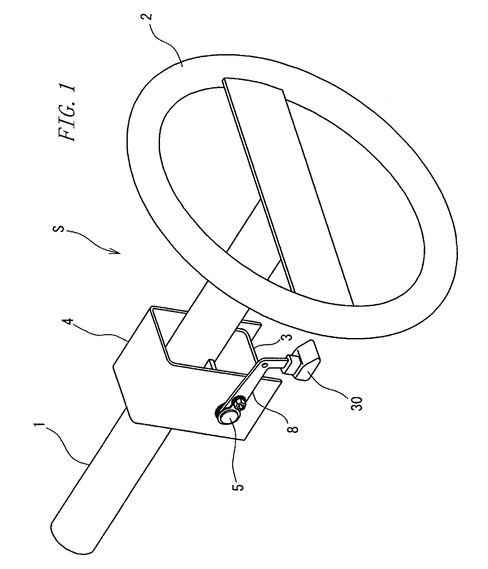
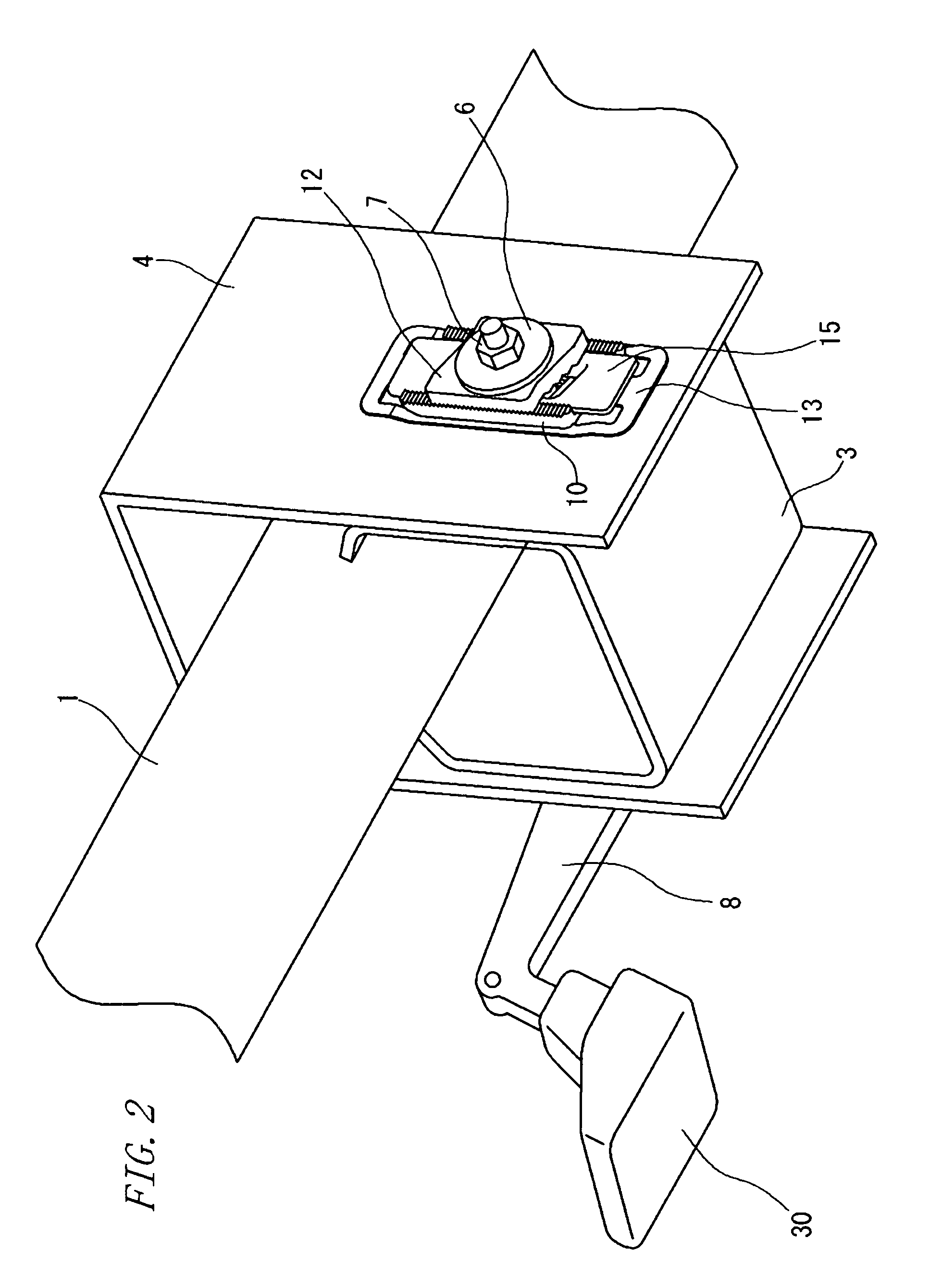
[0033]FIG. 1 is a perspective view showing an essential part of an adjustable steering apparatus S according to one embodiment of the invention. FIG. 2 is an enlarged fragmentary view of the adjustable steering apparatus S shown in FIG. 1.

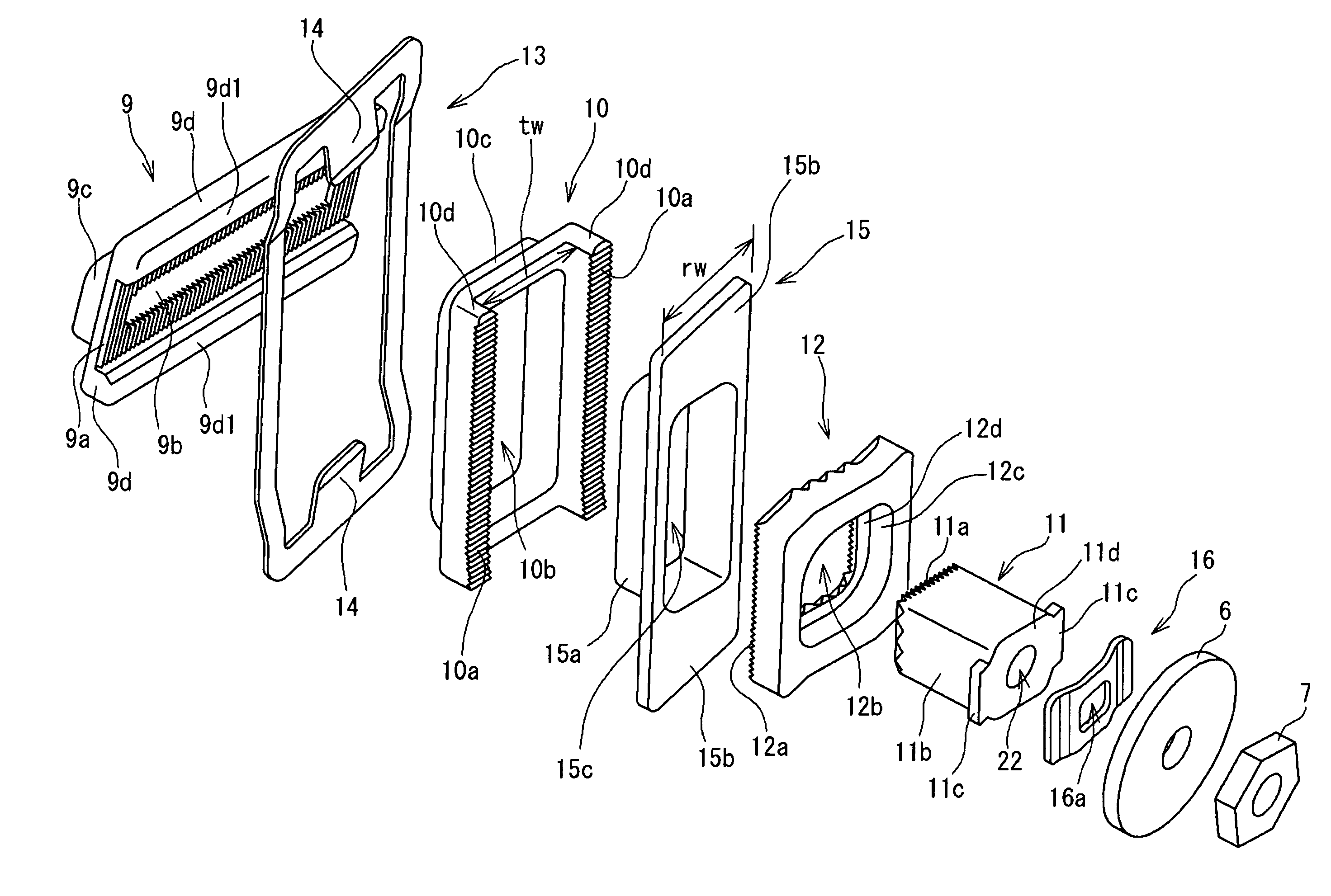
[0034]The adjustable steering apparatus S according to the embodiment is a steering apparatus which permits tilting and telescopic motions of a steering wheel 2 mounted to a distal end or an upper end (vehicular rearward end portion) of a column shaft (not shown) rotatably supported by a steering jacket 1. The steering apparatus includes: a movable bracket 3 to which the steering jacket 1 is fixed; and a stationary bracket 4 disposed externally of the movable bracket 3 and fixed to a vehicle body (not shown). A disk-like washer 6 is disposed at place near one end of a clamp b...


PUM


Abstract

An adjustable steering apparatus includes: a movable bracket to which a steering jacket including a steering wheel is fixed and to which a movable telescopic member having a tooth portion is fixedly mounted; a stationary bracket which is disposed externally of the movable bracket and fixed to a vehicle body, and to which a stationary tilt member having a tooth portion is fixedly mounted; a movable tilt member having a tooth portion meshingly engageable with the tooth portion of the stationary tilt member; and a stationary telescopic member having a tooth portion meshingly engageable with the tooth portion of the movable telescopic member. An elastic body for release from meshing engagement is disposed on an outer side of the stationary bracket, the elastic body being capable of urging the movable tilt member away from the stationary tilt member. The movable tilt member is engageable with the stationary telescopic member in order that the movable tilt member being disengaged from the stationary tilt member can bring the stationary telescopic member out of engagement with the movable telescopic member.

Description

BACKGROUND OF THE INVENTION[0001]The present invention relates to an adjustable steering apparatus. More particularly, the invention relates to an adjustable steering apparatus which utilizes a tooth-to-tooth meshing engagement for fixing or releasing a steering jacket including a steering wheel.[0002]A tiltable, telescopic steering apparatus has been known which permits a steering wheel in front of a driver to be tilted upward or downward for tilt adjustment and to be axially extended or retracted for adjustment in order that the driver may drive in an optimum position.[0003]Such a steering apparatus generally has a constitution wherein the steering jacket (jacket tube) rotatably supporting a column shaft having the steering wheel mounted to its distal end is fixed to a movable bracket vertically movable as clamped by an upper clamp (stationary bracket) fixed to a vehicle body. An operation lever is fixed to a nut in threaded engagement with a clamp bolt penetrating through these b...

Claims


Application Information

Patent Timeline
Patent Type & Authority Patents(United States)
IPC IPC(8): B62D1/18
CPCB62D1/184
Inventor MATSUI, ISAOUESAKA, YOTA
Owner JTEKT CORP
Why Eureka
Try Eureka