Method of controlling a working machine

a working machine and working technology, applied in steering controls, computation using non-denominational number representations, analog and hybrid computing, etc., can solve the problems of difficult for the operator to control the rotational actuator of the boring tool for a sustained period, and the difficulty of the operator to re-achieve the desired rotational speed of the boring bi

Active Publication Date: 2010-06-01
JCB COMPACT PRODS
View PDF45 Cites 45 Cited by
  • Summary
  • Abstract
  • Description
  • Claims
  • Application Information

AI Technical Summary

Benefits of technology

[0005]Thus a machine operator can use the memorised input to control the selected operating function rather than having to control the additional control to maintain an optimum input for the duration of the task.
[0016]The control system may include a selector switch for transferring control of the selected operating function to the additional control, and in an embodiment in which there is a second operator control for operating hydraulic actuators for effecting operating functions of the machine, the selector switch may be mounted on the second operator control. However, if such a selector switch is capable of selecting between a plurality of alternative operating functions to be controlled by the additional control, and transferring control of a selected one of the plurality of operating functions to the additional control, the selector switch may more conveniently be provided elsewhere, for example only, on a dashboard or other control panel of the working machine.

Problems solved by technology

When carrying out such a task, it can be advantageous for the rotational speed of the boring bit to be maintained at a certain level, but it can be difficult for an operator to control the boring tool rotational actuator for a sustained period to maintain the desired boring bit rotational speed, and / or the task may be interrupted, making it difficult for the operator to re-achieve the desired boring bit rotational speed.

Method used


Image

  • Method of controlling a working machine
  • Method of controlling a working machine
  • Method of controlling a working machine

Examples


Embodiment Construction

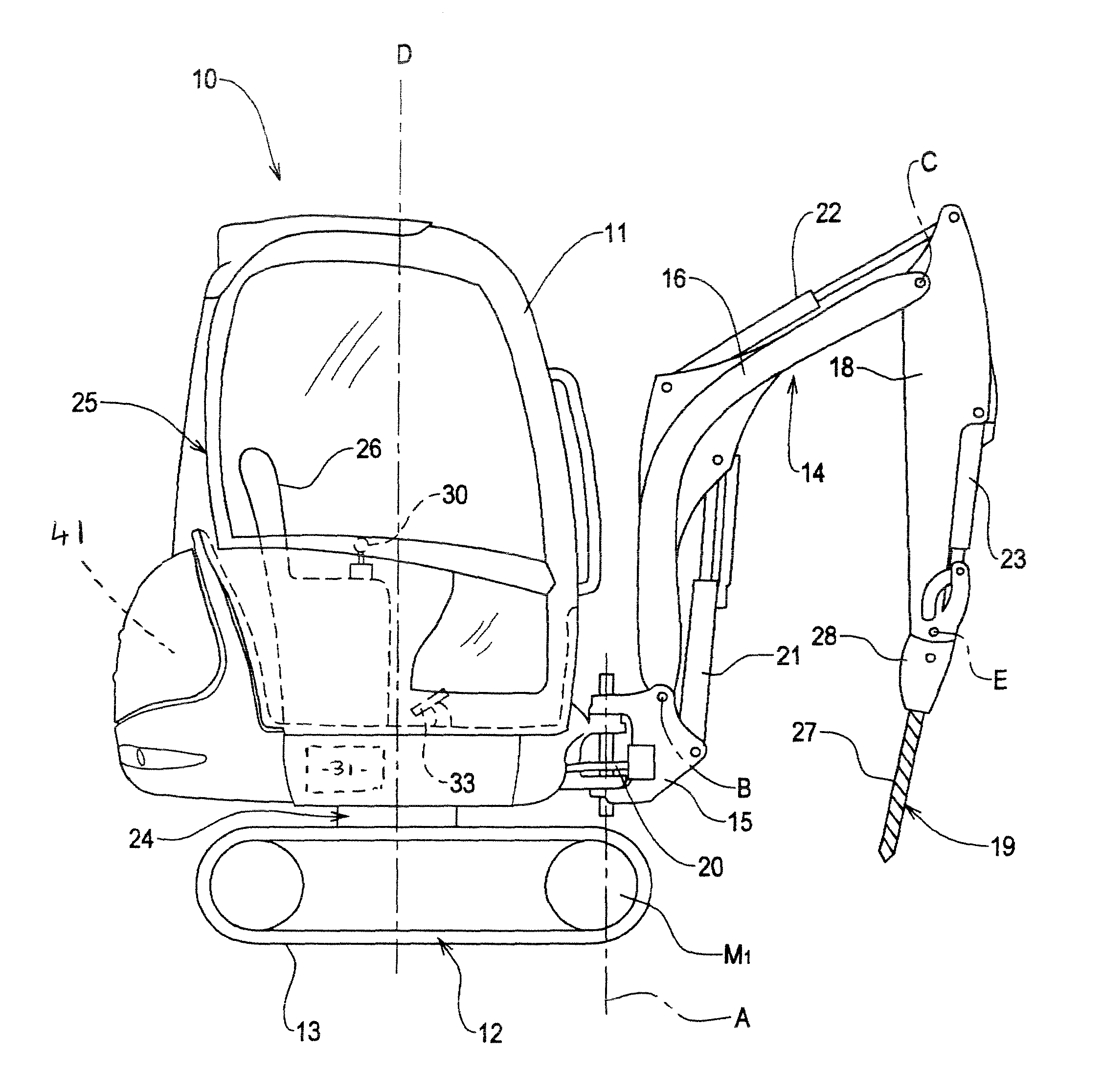
[0027]Referring to the drawings, there is shown a working machine 10 which in the example to be described with reference to the drawings is an excavating machine which includes a body 11 and a ground engaging structure 12, which in this example includes a pair of tracks 13, driven by respective hydraulically powered track motors one of which is indicated illustratively by the reference M1, through respective track drive sprockets. In this example, the body 11 is rotatable about a generally upright slew axis D relative to the ground engaging structure 12 by a hydraulic actuator which is a hydraulic motor, the general location for which is identified at 24.

[0028]It will be apparent from the description below that the invention may be applied to other than an excavator, e.g. a loading machine, and that such other kind of working machine may have an alternative ground engaging structure e.g. having ground engaging wheels rather than tracks.

[0029]A working machine 10 with which the inven...


PUM


Abstract

A method is described of operating a working machine which includes a body, a ground engaging structure, and a working arm carrying a working implement, and an operator control for operating hydraulic actuators for effecting operating functions of the machine, the operator control mounting an additional control which is controllable to operate at least one selected actuator for effecting a selected operating function, the additional control providing inputs to a control device which responds proportionally to operate the selected actuator, the method including controlling the additional control to operate the selected actuator, and with the additional control being controlled to provide an input to the control device to achieve a desired operation of the actuator, activating a memory mode whereby the control device memorises the input and continues to operate the selected actuator in accordance with the memorised input.

Description

BACKGROUND TO THE INVENTION[0001]This invention relates to a method of operating a working machine of the kind having a body, a ground engaging structure, and a working arm carrying a working implement.[0002]It is known for operating functions such as the movement of a working arm of a working machine to be effected by hydraulic actuators which may be linearly acting actuators such as hydraulic rams, or rotationally acting actuators such as hydraulic motors, which are controlled by an operator using controls, usually from within a cab located in or on the body of the machine. It is also known for the operator controls to include proportional controls, so that a hydraulic actuator is operated to effect an operating function in correspondence with the direction and the magnitude of a control input to its operator control.[0003]For example a working implement such as a boring tool may be carried by the working arm, and its operation i.e. speed of rotation of a boring bit, may be propor...

Claims


Application Information

Patent Timeline
Patent Type & Authority Patents(United States)
IPC IPC(8): G06F7/70G06F19/00G06G7/00G06G7/76
CPCE02F9/2004
Inventor MORRIS, DAVID ANDREWARGENTIERI, LUCIANOMAYER, ANDREW STUART
Owner JCB COMPACT PRODS
Why Eureka
Try Eureka