Solar-powered light pole and LED light fixture

a technology of led light fixtures and solar panels, which is applied in the field of solar-powered outdoor lighting, can solve the problems of not addressing or solving many of the problems of prior art, and the solar cells are typically visually distracting and/or aesthetically unappealing, so as to achieve efficient and long-lasting light production and enhance operation.

Inactive Publication Date: 2010-06-08
SOLARONE SOLUTIONS
View PDF31 Cites 146 Cited by
  • Summary
  • Abstract
  • Description
  • Claims
  • Application Information

AI Technical Summary

Benefits of technology

[0008]The preferred light pole according to the invention is similar in exterior appearance to conventional light poles, in that the pole profile is generally smooth and of generally the same or similar diameter all the way along the length of the pole. The photovoltaic panel fits snugly against the pole outer surface and requires no brackets, racks or other protruding structure. The preferred LED fixture is at or near the top of the pole, is generally a vertical cylinder of the same or similar diameter as the pole, and may be convectively cooled by air flow up through the pole. The preferred LED fixture eliminates the need for the difficult engineering task of adapting the many common styles of outdoor light fixtures to use LEDs. Further, because the preferred battery system is concealed either inside the pole, inside a base holding the pole, or buried below the grade level of the ground or street, there is no need for a large box or protruding battery structure on or near the pole.
[0009]In the event that the purchaser or public wish the lighting system to match or be reminiscent of previously-installed or other conventional street lights, a conventional-looking lighting fixture may be provided in addition to the preferred LED fixture. Said conventional-looking lighting fixture may extend horizontally or from atop the pole, and may be purely decorative, or may have a minimal or token light-emitting device therein. Such a decorative light fixture may more easily meet with approval from the public and / or may blend in with traditional street lights that remain in an area. By using a combination of the LED fixture and a decorative fixture, the single LED light-producing section may be engineered and installed, while preserving various aesthetic options for the city, county, or neighborhood and / or while allowing the new solar-powered lights to “blend in” with the street lights already in place. Further, the decorative light fixtures may be light-weight and designed to break-away in high winds or storms, thus minimizing the damage to the pole, surrounding property, and / or people.
[0011]In another embodiment, an outdoor light pole, having the features described above, is provided on, and hinged to, a portable base. In such an embodiment, the battery system may be located in, and provide additional weight for, the base.
[0013]In the preferred embodiments, venting and / or air channels are provided in the pole to allow cooling by natural convection air flow through the pole and the light fixture. Optionally, heating equipment may be provided in one or areas of the pole to protect equipment and / or enhance operation during extreme cold.
[0014]In other embodiments, the invention comprises the LED fixture without the street light pole, wherein the fixture may be connected to various other poles or stands, supports, fences and buildings. The LED fixture may be effective and aesthetically pleasing for various patio, driveway, entryway, commercial buildings, and / or other outdoor supports and structures, for efficient and long-lived light production.

Problems solved by technology

Such flat panels of solar cells are typically visually distracting and / or aesthetically unappealing, as they are a large protuberance from the street light and / or have the appearance of a large platform supported atop the street light.
Yoshida and the other prior art known to the inventor, however, do not address or solve many of the issues that the present inventor has found to be important in providing an efficient, economical, temperature-versatile, long-life, and aesthetically-pleasing solar-powered outdoor light system.

Method used


Image

  • Solar-powered light pole and LED light fixture
  • Solar-powered light pole and LED light fixture
  • Solar-powered light pole and LED light fixture

Examples


Embodiment Construction

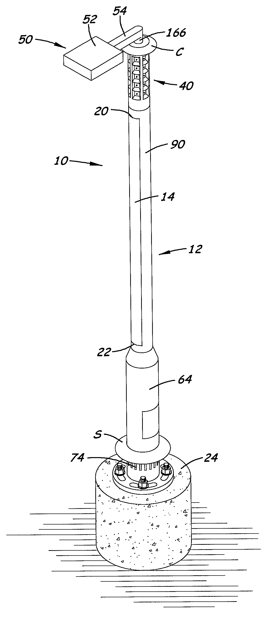
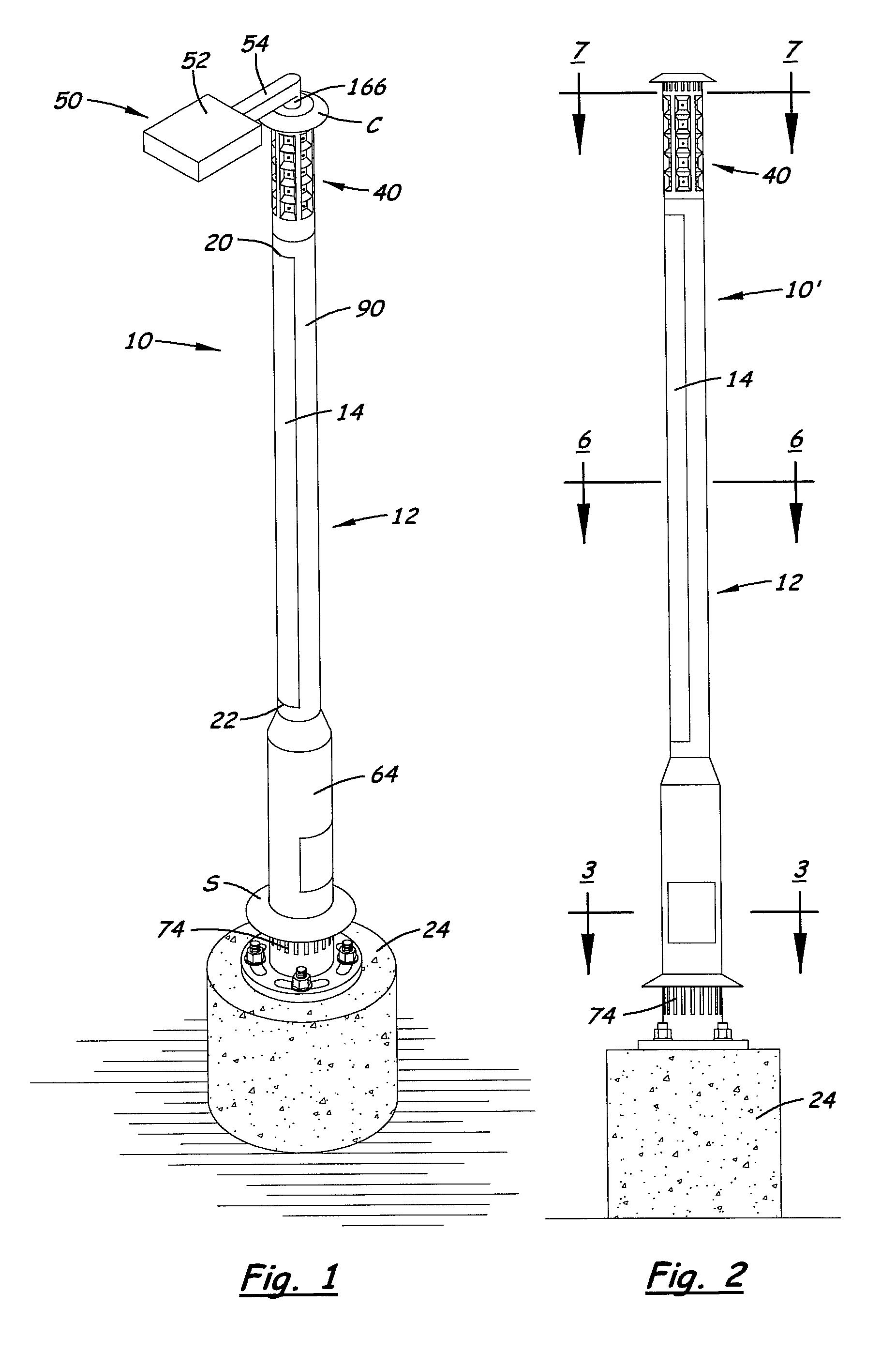
[0034]Referring to the Figures, there are shown several, but not the only, embodiments of the invented lighting system. FIG. 1 portrays one embodiment of a solar-powered street light 10, comprising a pole 12 with a panel 14 of thin-film photovoltaic material attached thereto. The panel 14 is preferably selected from commercially-available amorphous silicon (non-crystalline) photovoltaic materials that produce electrical energy when exposed to sunlight. One source of material for the panel 14 is Uni-Solar (United Solar Ovonic), which flexible, non-framed laminates that may be used in embodiments of the invention, under the name of UNI-SOLAR®“solar laminates” or “photovoltaic laminates.”

[0035]While currently-available flexible photovoltaic laminates, such as the UNI-SOLAR solar laminates are preferred, it is envisioned that thin-film light-active materials being developed, or to be developed in the future, may be used in embodiments of the invention, wherein said materials being devel...


PUM


Abstract

A solar-powered lighting system includes a flexible, wrap-around, preferably self-stick panel of photovoltaic laminate on the outside surface of a light pole. An LED light fixture is connected at or near the top of the pole and has the same or similar diameter as the pole. The LED light fixture has multiple columns and rows of LEDs and an interior axial space for air flow to cool the LEDs. The pole has vents and axial passage(s) for creating a natural updraft through at least a portion of the pole and the light fixture, for cooling of the photovoltaic panel interior surface, the LEDs, and / or other equipment inside the fixture or pole, and batteries provided inside the pole or pole base. A decorative additional fixture, which emulates conventional outdoor light fixtures, may be provided on the lighting system, wherein the decorative additional fixture includes no, or only a minimal, light source.

Description

[0001]This application claims priority of Provisional Application 60 / 888,002, filed Feb. 2, 2008, the entire disclosure of which is incorporated herein by this reference.BACKGROUND OF THE INVENTION[0002]1. Field of the Invention[0003]This invention relates to solar-powered outdoor lighting. More specifically, the invention relates to pole-mounted lighting that is powered by solar energy by means of a photovoltaic panel on the outside surface of the pole and batteries or other storage devices. The invented outdoor lighting has a structure, shape, and profile that look much like conventional street lights, for matching pre-existing street lights and / or accommodating local or governmental aesthetic preferences.[0004]2. Related Art[0005]Solar-powered street lights and light fixtures have been developed in the past. For example, the patent literature includes: Robbins (U.S. Pat. No. 5,149,188, issued Sep. 22, 1992); Yoshida (U.S. Pat. No. 6,060,658, issued May 9, 2000); Wang (U.S. Pat. N...

Claims


Application Information

Patent Timeline
Patent Type & Authority Patents(United States)
IPC IPC(8): F21S13/10F21V29/00
CPCF21S8/083F21S8/086F21S9/037F21V29/004F21V29/83H01L31/0521H02S40/38F21V23/0435F21V23/0442F21W2131/103F21Y2101/02Y02E10/50F21W2111/00F21Y2115/10Y02B20/72Y02E70/30
Inventor MYER, SETH JAMISON
Owner SOLARONE SOLUTIONS
Why Eureka
Try Eureka