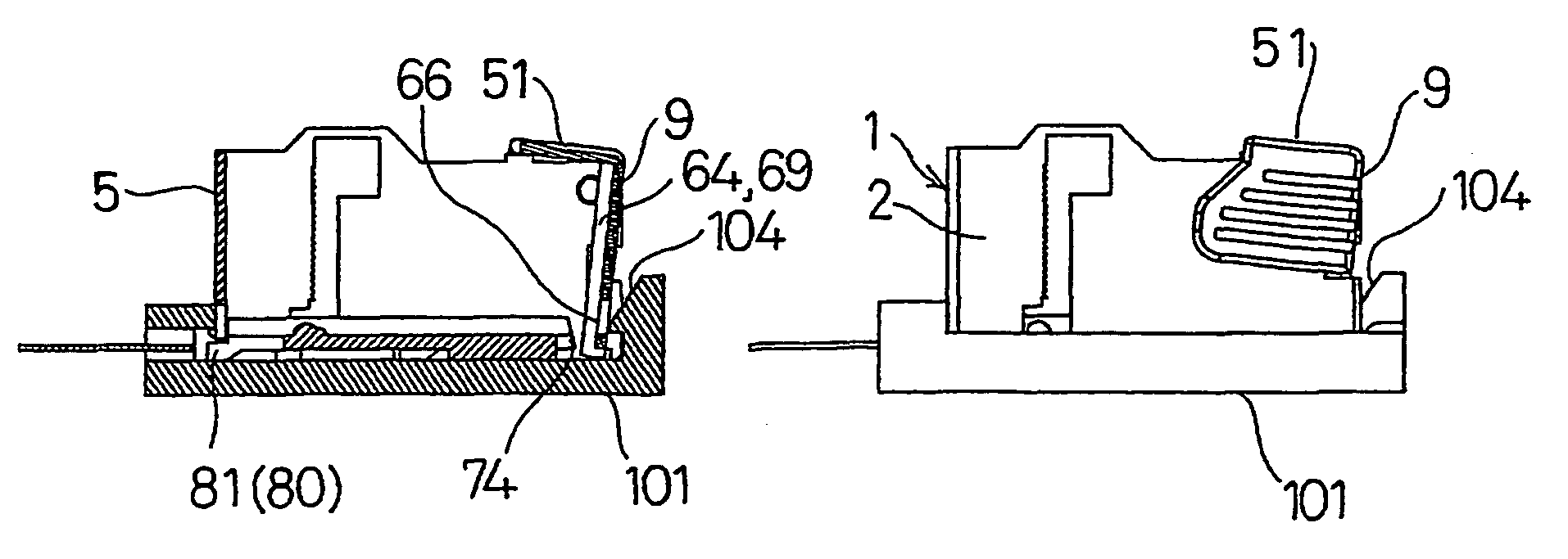
[0168]Furthermore, a projection 109 resting on the resting member 47 of the covering member 45 provided on the front wall 5 of the refill 1 for staples is provided in the cartridge 105. A cover 113 is installed in the rear portion of the cartridge 105 through a link member 112. The cover 113 is installed in a reclosable manner, and is energized in the closing direction with an elastic member such as a spring. The above cover 113 has a function as a lid by which the accommodation section 102 in the stapler 100 is closed, and a function by which the cartridge 105 is unlocked, and a member as a knob which is held with fingers when the cartridge 105 is pulled out after the cartridge 105 is unlocked. The cartridge 105 has a configuration in which the cartridge 105 is fixed by being pushed into the cartridge accommodation section 102, fixing of the cartridge 105 is released by pulling the cover 113, and the cartridge 105 is pulled out in the direction in which the cartridge 105 is removed.
[0203]Then, a use mode of the cartridge 200A for staple sheets according to the above-described configuration will be explained. In the first place, the control lever 223 is rotated to open the holding section 207 of the cartridge body 201 wide (FIG. 17 and FIG. 19(A)). Subsequently, the refill case 200B loading the staple sheets 230 inside is put into the holding section 207 from above at an angle for setting (refer to FIG. 18). Then, the control lever 223 is rotated in such a way that the refill holder 202, and, at the same time, the covering member 212 cover the refill case 200B. Subsequently, when the refill holder 202 is rotated to a limit for the rotation, the lower surface of the arm piece 215 is engaged with the upper surface of both side plates 204 in the cartridge body 201 as shown in FIG. 19(A) and FIG. 19(B), and, at the same time, the locking hook 216 is engaged with the locking hole 209 in the side plate 204 (refer to FIG. 22). At the same time, the engaging section located in the rear portion of the refill holder 202 pushes the rear surface of the refill case 200B forward, and the push lever 217 presses the upper surface of the cover plate 228, as shown in FIG. 20. Thereby, the refill case 200B is fixed in the cartridge body 201.
[0203]Then, a use mode of the cartridge 200A for staple sheets according to the above-described configuration will be explained. In the first place, the control lever 223 is rotated to open the holding section 207 of the cartridge body 201 wide (FIG. 17 and FIG. 19(A)). Subsequently, the refill case 200B loading the staple sheets 230 inside is put into the holding section 207 from above at an angle for setting (refer to FIG. 18). Then, the control lever 223 is rotated in such a way that the refill holder 202, and, at the same time, the covering member 212 cover the refill case 200B. Subsequently, when the refill holder 202 is rotated to a limit for the rotation, the lower surface of the arm piece 215 is engaged with the upper surface of both side plates 204 in the cartridge body 201 as shown in FIG. 19(A) and FIG. 19(B), and, at the same time, the locking hook 216 is engaged with the locking hole 209 in the side plate 204 (refer to FIG. 22). At the same time, the engaging section located in the rear portion of the refill holder 202 pushes the rear surface of the refill case 200B forward, and the push lever 217 presses the upper surface of the cover plate 228, as shown in FIG. 20. Thereby, the refill case 200B is fixed in the cartridge body 201.
[0171]When a plurality of sheets of paper are filed in the above-described configuration, the stapler body 1 has a configuration in which a sheet-type connected staple is sent forward with the sending pawl, a staple located at the tip is bent into a U-shaped one, the above-described sheets of paper are stapled with the above bent staple, using the driver, and the tip of the staple is bent for filing after the above stapling to complete processing.
[0171]When a plurality of sheets of paper are filed in the above-described configuration, the stapler body 1 has a configuration in which a sheet-type connected staple is sent forward with the sending pawl, a staple located at the tip is bent into a U-shaped one, the above-described sheets of paper are stapled with the above bent staple, using the driver, and the tip of the staple is bent for filing after the above stapling to complete processing.
[0171]When a plurality of sheets of paper are filed in the above-described configuration, the stapler body 1 has a configuration in which a sheet-type connected staple is sent forward with the sending pawl, a staple located at the tip is bent into a U-shaped one, the above-described sheets of paper are stapled with the above bent staple, using the driver, and the tip of the staple is bent for filing after the above stapling to complete processing.
[0171]When a plurality of sheets of paper are filed in the above-described configuration, the stapler body 1 has a configuration in which a sheet-type connected staple is sent forward with the sending pawl, a staple located at the tip is bent into a U-shaped one, the above-described sheets of paper are stapled with the above bent staple, using the driver, and the tip of the staple is bent for filing after the above stapling to complete processing.
[0171]When a plurality of sheets of paper are filed in the above-described configuration, the stapler body 1 has a configuration in which a sheet-type connected staple is sent forward with the sending pawl, a staple located at the tip is bent into a U-shaped one, the above-described sheets of paper are stapled with the above bent staple, using the driver, and the tip of the staple is bent for filing after the above stapling to complete processing.
[0215]Here, there is required only a configuration in which a pressing unit is provided in a refill holder, and the present invention is not limited to the configurations shown in the drawings. There may be applied, for example, a configuration in which a staple push lever 217 (energizing unit) is formed like the arm member 106 shown in FIG. 9(A) through FIG. 9(F), the lever 217 is engaged with both ends of the guide shaft 75, the guide shaft 75 is energized by an energizing unit, and the cover plate (pressing member) 226 is energized in the pressing direction (in which the staple sheets 230 are laminated). That is, there may be applied a configuration in which, when the main body (refill body) 227 is installed in the cartridge 200A, the guide shaft 75 is engaged with the staple push lever 217 (energizing unit) provided in the cartridge 200A, and the cover plate (pressing member) 226 is energized by an energizing unit in the pressing direction (in which the staple sheets 230 are laminated).
[0215]Here, there is required only a configuration in which a pressing unit is provided in a refill holder, and the present invention is not limited to the configurations shown in the drawings. There may be applied, for example, a configuration in which a staple push lever 217 (energizing unit) is formed like the arm member 106 shown in FIG. 9(A) through FIG. 9(F), the lever 217 is engaged with both ends of the guide shaft 75, the guide shaft 75 is energized by an energizing unit, and the cover plate (pressing member) 226 is energized in the pressing direction (in which the staple sheets 230 are laminated). That is, there may be applied a configuration in which, when the main body (refill body) 227 is installed in the cartridge 200A, the guide shaft 75 is engaged with the staple push lever 217 (energizing unit) provided in the cartridge 200A, and the cover plate (pressing member) 226 is energized by an energizing unit in the pressing direction (in which the staple sheets 230 are laminated).
[0193]Though the refill 1 for staples which can laminate and accommodate the sheet-type connected staples S has been explained in the above-described embodiment, the refill 1a for staples may be configured to accommodate rolled-sheet-type connected staples as shown in FIG. 15(A) through FIG. 15(H). This refill 1a for staples is configured to be installed in a stapler body, or a cartridge provided in the stapler body, and includes a cylindrical refill body 2a which holds the rolled-sheet-type connected staples.

