Surgical stapling instrument with improved firing trigger arrangement

a technology of firing trigger and surgical stapling, which is applied in the direction of surgical staples, surgical forceps, paper/cardboard containers, etc., can solve the problems of increasing the time needed to complete surgery and impede the advancement of the actuator knob

Active Publication Date: 2010-08-03
CILAG GMBH INT
View PDF596 Cites 1684 Cited by
  • Summary
  • Abstract
  • Description
  • Claims
  • Application Information

AI Technical Summary

Benefits of technology

[0007]In at least one form of the present invention, a surgical stapling instrument can include an actuator knob which can be moved from one side of the stapling instrument to another side in order to reposition the actuator knob without having to reposition the stapling instrument within a surgical site. In various embodiments, a stapling instrument can include a staple cartridge having at least two rows of staples stored therein, a pusher bar, a staple driver operably engaged with the pusher bar, wherein the staple driver can be configured to eject the staples from the staple cartridge, and an anvil configured to deform the staples when they are deployed from the staple cartridge. In at least one embodiment, the stapling instrument can further include a housing having a first side and a second side and, in addition, an actuator knob rotatably mounted to the pusher bar wherein the actuator knob can be configured to be rotated between a first position in which the actuator knob can be moved along the first side of the housing and a second position where the actuator knob can be configured to be moved along a second side of the housing.
[0008]In at least one form of the present invention, a surgical stapling instrument can comprise one or more actuator knobs which can be operably engaged with and disengaged from a pusher bar in order to selectively utilize the actuator knobs. In various embodiments, a stapling instrument can include one or more rotatable actuator knobs which can be rotated between a first, retracted position in which they are operably disengaged from the pusher bar and a second, extended position in which they are operably engaged with the pusher bar. In at least one embodiment, a surgeon can selectively extend an actuator knob to advance the pusher bar such that the selected actuator knob does not interfere, or at least substantially interfere, with the surrounding tissue. The other actuator knob, or knobs, can remain in a retracted, disengaged position such that they do not have to be advanced with the pusher bar and / or do not substantially extend from the outer perimeter of the surgical stapling instrument.

Problems solved by technology

In at least one circumstance, though, the actuator knob, as it can extend outwardly from the surgical instrument, can unintentionally contact tissue surrounding the surgical site and, as a result, the tissue may impede the advancement of the actuator knob.
In such circumstances, a surgeon may have to force the actuator knob past the tissue and / or re-position the stapling instrument which can increase the time needed to complete the surgery.

Method used


Image

  • Surgical stapling instrument with improved firing trigger arrangement
  • Surgical stapling instrument with improved firing trigger arrangement
  • Surgical stapling instrument with improved firing trigger arrangement

Examples


Embodiment Construction

[0044]Certain exemplary embodiments will now be described to provide an overall understanding of the principles of the structure, function, manufacture, and use of the devices and methods disclosed herein. One or more examples of these embodiments are illustrated in the accompanying drawings. Those of ordinary skill in the art will understand that the devices and methods specifically described herein and illustrated in the accompanying drawings are non-limiting exemplary embodiments and that the scope of the various embodiments of the present invention is defined solely by the claims. The features illustrated or described in connection with one exemplary embodiment may be combined with the features of other embodiments. Such modifications and variations are intended to be included within the scope of the present invention.

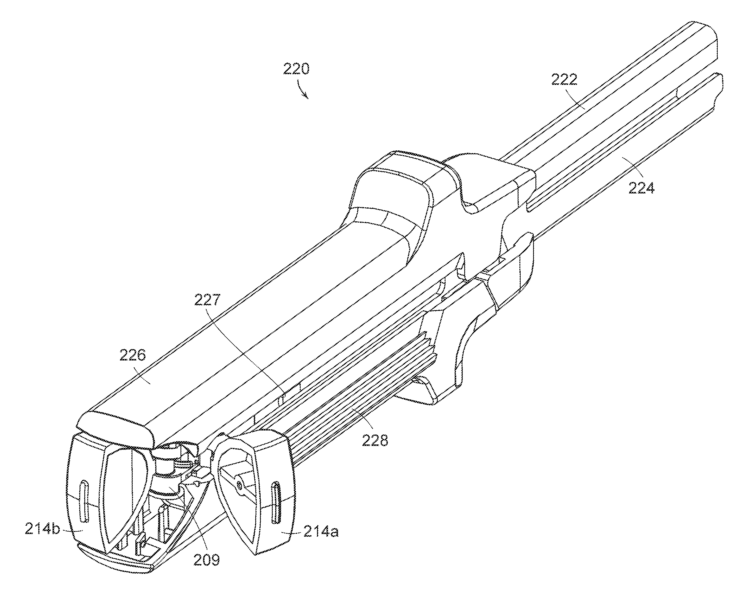
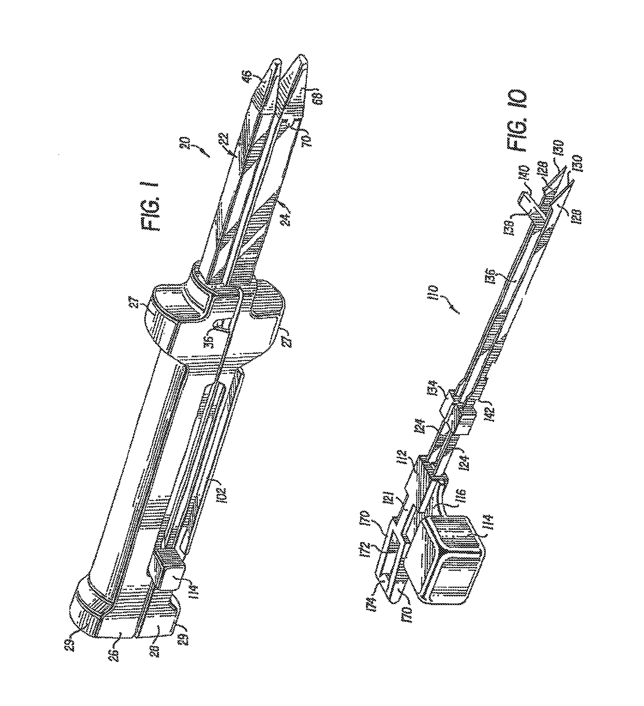
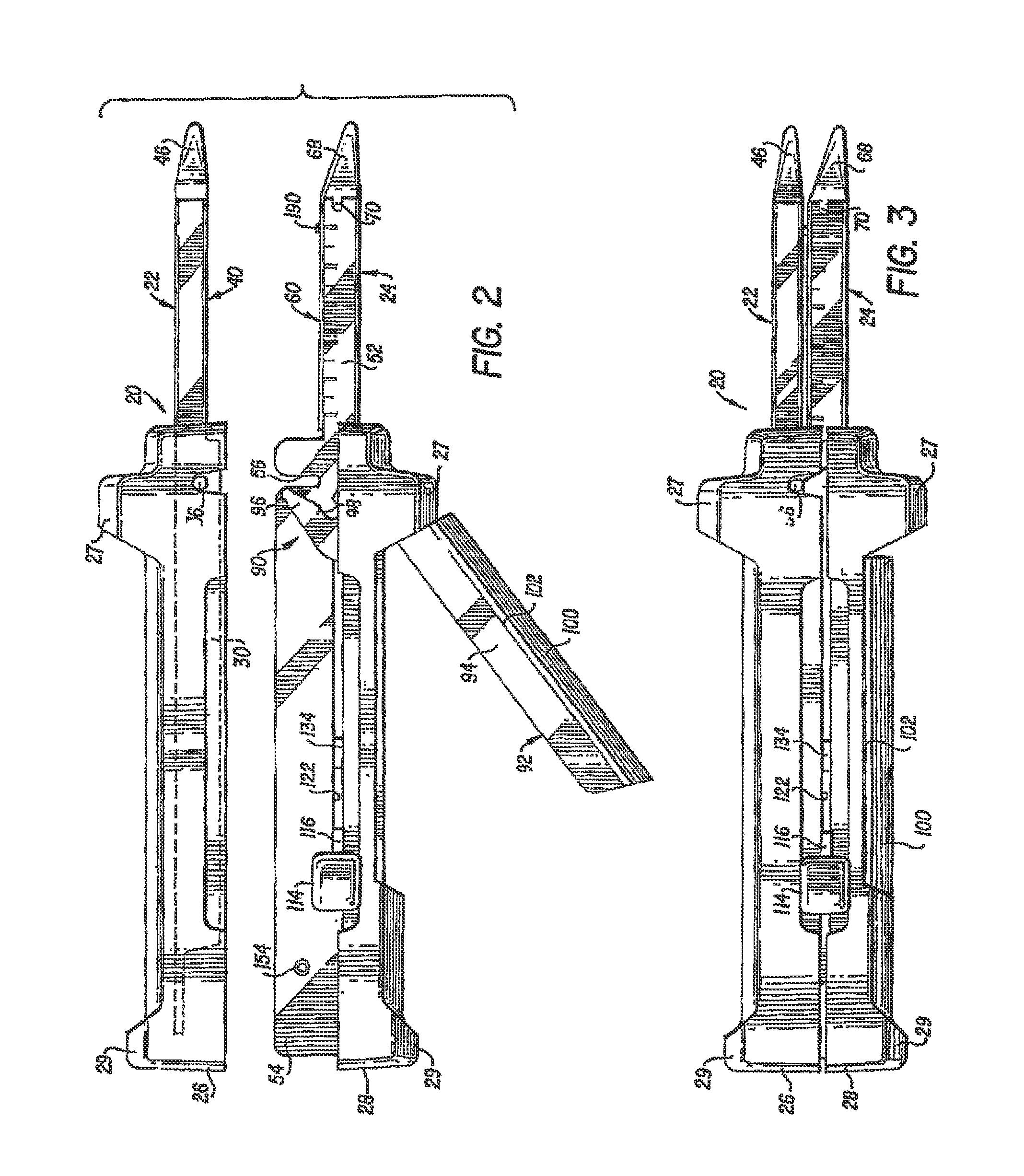
[0045]Referring to FIGS. 1 and 2, a linear anastomotic stapling instrument, generally 20, can comprise an upper elongated anvil carrying jaw member 22 and a lower ...


PUM

PropertyMeasurementUnit
forceaaaaaaaaaa
timeaaaaaaaaaa
perimeteraaaaaaaaaa

Abstract

A surgical stapling instrument including an actuator knob which can be moved from one side of the stapling instrument to another side in order to reposition the actuator knob without having to reposition the stapling instrument within a surgical site. A stapling instrument can include a pusher bar, a housing having a first side and a second side, and an actuator knob rotatably mounted to the pusher bar wherein the actuator knob can be configured to be rotated between a first position in which the actuator knob can be moved along the first side of the housing and a second position where the actuator knob can be moved along a second side of the housing. Alternatively, a surgical stapling instrument can comprise one or more actuator knobs which can be operably engaged and disengaged with a pusher bar in order to selectively utilize the actuator knobs.

Description

BACKGROUND[0001]i. Technical Field[0002]The present invention relates to a surgical stapling instrument and, in various embodiments, to a gastrointestinal anastomotic stapling instrument for producing one or more rows of staples.[0003]ii. Background of the Related Art[0004]In recent years, there has been an increasing tendency for surgeons to use stapling instruments to suture body tissues such as a lung, an esophagus, a stomach, a duodenum and / or other organs in the intestinal tract. The use of an appropriate stapling instrument in many instances may perform a better job in less time and simplify previously difficult surgical procedures such as gastrointestinal anastomoses. Previous linear two and four row cutting staplers comprised cartridge-less instruments into which staples were individually hand-loaded. Other previous devices have included a presterilized disposable staple loading unit and a cutting member which could be utilized for dividing the tissue and forming the rows of...

Claims


Application Information

Patent Timeline
Patent Type & Authority Patents(United States)
IPC IPC(8): A61B17/068
CPCA61B17/07207A61B2017/2912A61B2017/00367A61B17/115
Inventor BAXTER, III, CHESTER O.BEDI, JAMES
Owner CILAG GMBH INT
Why Eureka
Try Eureka