Pulse container for an insect electrocutor

a technology of electric pulses and containers, applied in the field of pulse counters, can solve the problems of inability to count and display the number of harmful insects killed, the apparatus is a mechanically ambitious product, and the installation of apparatuses is difficult, etc., to achieve the effect of reducing agricultural production costs, easy and inexpensive counting of electric pulses, and avoiding costs and dangers

Inactive Publication Date: 2010-08-24
NAT AGRI & FOOD RES ORG
View PDF18 Cites 13 Cited by
  • Summary
  • Abstract
  • Description
  • Claims
  • Application Information

AI Technical Summary

Benefits of technology

[0018]The electric pulse counter employing a field server further comprises a fan built into the field server or attached to the counter module for introducing air into the case of the counter module and producing airflows through the counter module and exiting the small holes formed therein for actively carrying molecules of the pheromone or attractant gas produced by the insect attracting unit out of the counter module to encourage insect attraction. The fan rotation is temporarily accelerated to increase the rate of airflow for discharging insects from the insect electrocutor that have been seared by electrical shock and caked on the surfaces of the electrodes or insect remains and dust accumulating on the insect attracting unit and on the inner bottom surface of the counter module. The airflows produced by the fan also functioning to prevent rain from entering the counter module, preventing short circuits caused by raindrops from occurring in the insect electrocutor.
[0021]Further, a small camera capable of communicating with the field server is provided in the insect electrocutor for taking images of electrocuted insects that have accumulated on the inner bottom surface of the counter module or on the surfaces of the electrodes to aid in monitoring the numbers and types of insects that have been killed in order to confirm, correct, or compensate for the precision of pulse counts measured with the electric pulse counter.
[0023]By using a coil to detect an electromagnetic field generated near the insect electrocutor by a spark therein, the system of the present invention can reliably count electric pulses easily and inexpensively, without the costs and danger associated with directly connecting a counter to a high-voltage current in the insect electrocutor.
[0024]The system can be implemented simply by providing the electromagnetic field coil and AC signal converter circuit near the insect electrocutor disposed in the agricultural region. Using the wireless LAN function of the field server to connect to the Internet, the system can collect such environmental data as temperature, humidity, solar radiation, and soil moisture measured by various sensors provided in the field server from remote locations in real time and can provide this data in response to queries from agricultural administrators or researchers by storing the data as time series data in a remote server, enabling the administrators or researchers to scientifically predict outbreaks of insects based on the environmental data and analyses on the relationships between environmental conditions and insect outbreaks. Since measures such as pesticide application are unnecessary when there is no danger of harmful insects, agricultural production costs can be reduced.
[0026]The number of mosquitoes or other harmful insects that have been killed in a public park or other outdoor space can be displayed on a Web page at fixed intervals using maps and graphs so that the end-user can confirm in real time which regions are infested with mosquitoes or other harmful insects. This data can help the end-user to select an appropriate campsite, picnic location, or the like.

Problems solved by technology

Due to their large size and costliness, existing apparatuses for counting harmful insects are difficult to install and have been limited to use by research institutes and government agencies.
However, the apparatuses are unable to count and display the number of harmful insects killed.
However, this apparatus is a mechanically ambitious product and is costly to manufacture.
Although the apparatus has good counting precision, the mechanism needed to count insects reliably is complex and expensive and not suited to a compact design.
The apparatus is also unable to collect and distribute data via the Internet.
Further, maintenance can be cumbersome if the interior of the apparatus becomes clogged with insects or in the event of another malfunction.
Further, since a cell phone is used to transmit insect counts to remote locations, operating costs that include monthly telephone charges are considerable.
On the other hand, the common insect electrocuting apparatus, while inexpensive, cannot count the number of insects that are killed and, hence, cannot transmit such count data to remote locations.
However, this process involves many problems, including additional costs to the user for dismantling the apparatus and connecting a counting circuit, added noise in the counting circuit, and the danger of electrocution to the user.
Further, when using a conventional device for counting insects, a large number of personnel are needed for verifying that the device is counting accurately and for correcting incorrect counts.
Moreover, the workers must travel to the site and conduct observations over a long period of time.
The cost required for this work can be excessive when the devices are installed at numerous locations, and particularly when the distance to the installation points is great.
Further, the appearance and migration of insects is greatly affected by many environmental factors, such as atmospheric temperature, soil moisture, and wind.
Conventionally, insect counting and environmental measurements have been performed independently as it is difficult to perform both simultaneously in real time.

Method used


Image

  • Pulse container for an insect electrocutor
  • Pulse container for an insect electrocutor
  • Pulse container for an insect electrocutor

Examples


Embodiment Construction

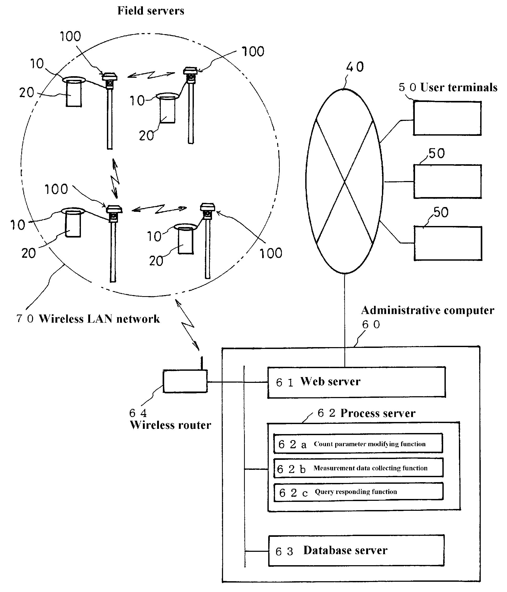
[0077]FIG. 1 is an explanatory diagram conceptually illustrating the structure of a pulse counter for counting electric pulses using field servers 100 according to a preferred embodiment of the present invention.

[0078]The pulse counter is configured of one or a plurality of field servers 100 connected to a wireless LAN network 70, an internet 40, an administrative computer 60 operated by an administrator in charge of managing the field servers 100, and user terminals 50 connected to the internet 40.

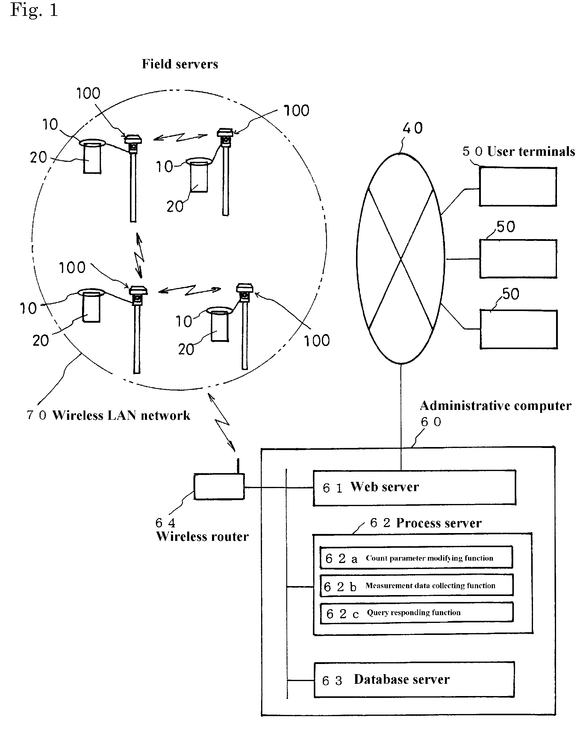
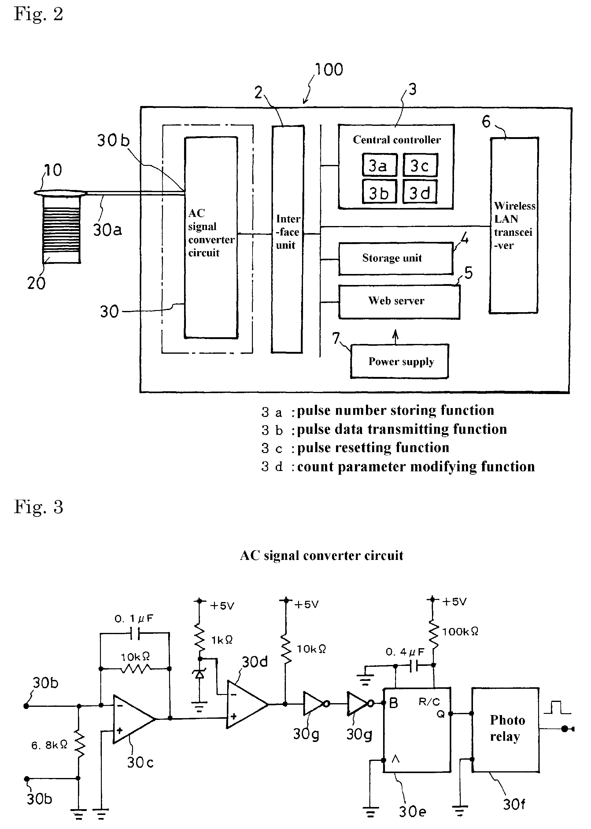
[0079]An insect electrocutor 20 is positioned near each of the field servers 100 for attracting insects present in the agricultural region and killing them by electrical discharge between electrodes to which a high voltage is applied. An electromagnetic detection coil 10 is disposed above or around the insect electrocutor 20 for detecting changes in the electromagnetic field caused by electrical discharges. An AC signal converter circuit 30 (see FIG. 2) is disposed in each field server 10...


PUM


Abstract

An electric pulse counter for counting and recording the number of insects killed in a commercial insect electrocutor through an on-site field server is disclosed. The pulse counter is configured of field servers 100, an internet 40, an administrative computer 60, and user terminals 50. An insect electrocutor 20 is positioned near each of the field servers 100 for attracting insects present in the agricultural region and killing them by electrical discharge. An electromagnetic detection coil 10 is disposed above or around the insect electrocutor 20 for detecting changes in the electromagnetic field caused by such electrical discharges. An AC signal converter circuit 30 is disposed in each field server 100 and connected to the lead wire of the corresponding electromagnetic detection coil 10 for generating a digital count pulse from the signal outputted by the electromagnetic detection coil 10. The count pulse is accumulated in a storage unit 4 in the field server and the accumulated value is transmitted to the administrative computer 60 in response to a request therefrom. The administrative computer 60 functions as a Web server to provide this data to users via the Internet.

Description

RELATED APPLICATIONS[0001]The present application is based on, and claims priority from, Japanese Application Number 2007-004265, filed Jan. 12, 2007, the disclosure of which is hereby incorporated by reference herein in its entirety.BACKGROUND OF THE INVENTION[0002]1. Field of the Invention[0003]The present invention relates to a pulse counter for counting and recording the number of insects killed in an insect-electrocuting apparatus by detecting the number of electric pulses generated in the apparatus in order to predict outbreaks of agricultural pests.[0004]2. Description of the Related Art[0005]It is desirable to count populations of harmful insects in agricultural regions in real time in order to predict outbreaks of agricultural pests and thereby prevent crop damage by such pests. Due to their large size and costliness, existing apparatuses for counting harmful insects are difficult to install and have been limited to use by research institutes and government agencies.[0006]A...

Claims


Application Information

Patent Timeline
Patent Type & Authority Patents(United States)
IPC IPC(8): A01M1/22
CPCA01M1/026A01M1/223G07C3/04
Inventor HIRAFUJI, MASAYUKIYOICHI, HIDEO
Owner NAT AGRI & FOOD RES ORG
Why Eureka
Try Eureka