High-pressure grouting device for bridge bottom reinforcement in high temperature environment

A high-temperature environment, high-pressure grouting technology, which is applied in bridge construction, bridge erection/assembly bridges, etc., can solve problems such as the difference between the internal and external pressure of grouting equipment, affect the effect of bridge reinforcement, and the bursting of grouting pipes, etc., to reduce the temperature , prolong the service life, and promote the effect of rapid evaporation of temperature

Active Publication Date: 2018-12-21
安徽升建工程管理有限公司
View PDF5 Cites 4 Cited by
  • Summary
  • Abstract
  • Description
  • Claims
  • Application Information

AI Technical Summary

Problems solved by technology

[0002] When the car passes over the bridge, it will cause the road surface of the bridge to vibrate. In the hot summer, thermal expansion and contraction will cause cracks at the bottom of the bridge. For this reason, the bottom of the bridge needs to be reinforced, using high-pressure grouting equipment Repair the cracks that appear. However, when the traditional high-pressure grouting equipment is used in a high-temperature environment, there will be a large difference in the internal and external pressure of the grouting equipment due to the high temperature. The large pressure difference will cause the grouting pipe to burst. Thus affecting the effect of bridge reinforcement, for this reason, we propose a high-pressure grouting equipment for bridge bottom reinforcement under high temperature environment

Method used


Image

  • High-pressure grouting device for bridge bottom reinforcement in high temperature environment
  • High-pressure grouting device for bridge bottom reinforcement in high temperature environment
  • High-pressure grouting device for bridge bottom reinforcement in high temperature environment

Examples


Embodiment Construction

[0021] In order to make the technical means, creative features, goals and effects achieved by the present invention easy to understand, the present invention will be further described below in conjunction with specific embodiments.

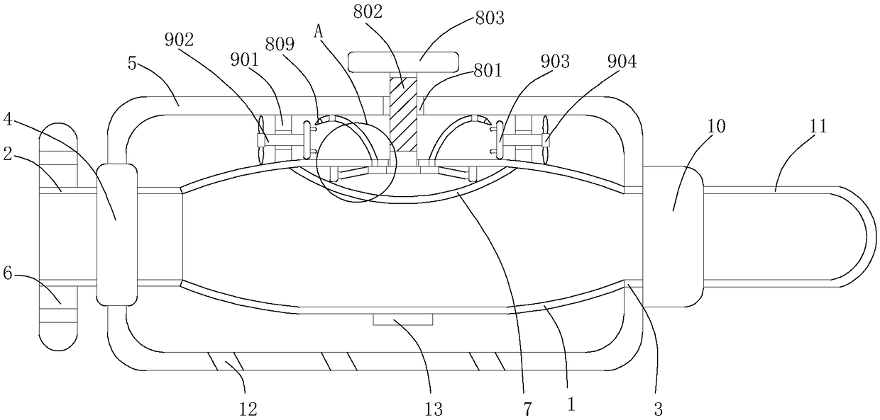
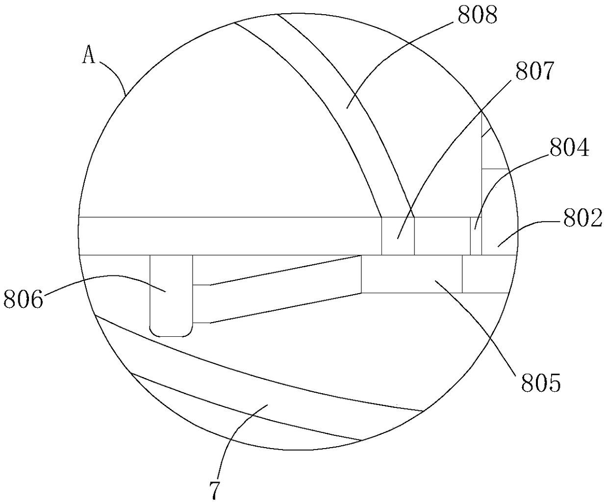
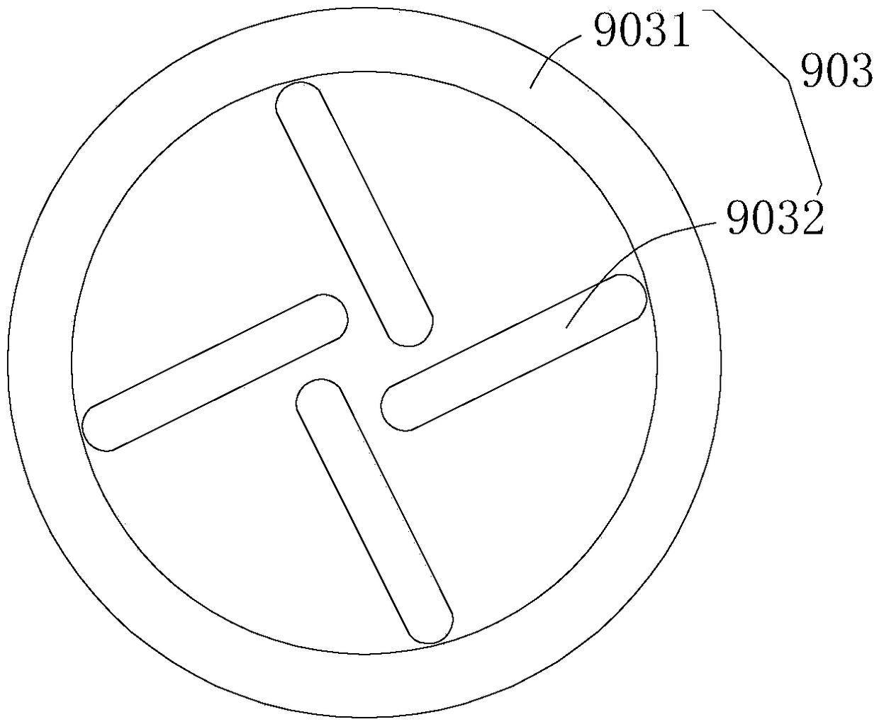
[0022] see Figure 1-4 , a high-pressure grouting equipment for reinforcing the bottom of a bridge in a high-temperature environment, comprising a grouting chamber 1, a grout feeding pipe 2, a grouting pipe 3, a sleeve pipe 4, a pressure regulating chamber 5, a ventilating diaphragm 7, a pressure regulating mechanism 8, two A cooling mechanism 9, a metering chamber 10, a grout outlet pipe 11, a flow hole 12, a temperature sensor 13 and a temperature display 14, the grout inlet pipe 2 is fixedly connected to the left end of the grouting chamber 1, and the grouting pipe 3 is fixedly connected to the grouting chamber 1, the casing 4 is fixedly socketed on the outer surface of the grouting pipe 2, the pressure regulating chamber 5 is fixedly socketed ...


PUM


Abstract

The invention relates to the technical field of bridge maintenance, and discloses a high-pressure grouting device for bridge bottom reinforcement under high temperature environment, Including groutingchamber, Slurry inlet pipe, slurry guide pipe, casing, surge chamber, breathable diaphragm, pressure regulator, Two cooling mechanisms, a metering chamber, a slurry outlet pipe and a circulation hole, wherein the slurry inlet pipe is fixedly communicated with the left end of the slurry injection chamber, the slurry guide pipe is fixedly communicated with the right end of the slurry injection chamber, the sleeve is fixedly sleeved on the outer surface of the slurry inlet pipe, the surge chamber is fixedly sleeved on the outer surface of the sleeve and the slurry guide pipe, and the air permeable diaphragm is fixed on the middle of the top wall of the slurry injection chamber. The air pressure in the grouting chamber can be dredged from the two exhaust holes, the air intensity difference inside and outside the grouting chamber can be reduced, the grouting chamber can be prevented from cracking due to the larger pressure difference, the airflow flow rate between the grouting chamber andthe surge chamber can be accelerated, the temperature on the outer surface of the grouting chamber can be rapidly evaporated, and the effect of lowering the temperature of the grouting chamber can beachieved.

Description

technical field [0001] The invention relates to the technical field of bridge maintenance, in particular to a high-pressure grouting equipment for reinforcing the bottom of a bridge in a high-temperature environment. Background technique [0002] When the car passes over the bridge, it will cause the road surface of the bridge to vibrate. In the hot summer, thermal expansion and contraction will cause cracks at the bottom of the bridge. Therefore, it is necessary to reinforce the bottom of the bridge and use high-pressure grouting equipment Repair the cracks that appear. However, when the traditional high-pressure grouting equipment is used in a high-temperature environment, there will be a large difference in the internal and external pressure of the grouting equipment due to the high temperature. The large pressure difference will cause the grouting pipe to burst. Thus affecting the effect of bridge reinforcement, for this reason, we propose a high-pressure grouting equipm...

Claims


Application Information

Patent Timeline
Patent Type & Authority Applications(China)
IPC IPC(8): E01D21/00
CPCE01D21/00
Inventor 吴渊
Owner 安徽升建工程管理有限公司
Why Eureka
Try Eureka