Mounting device for orthodontic retainer elements and a method of maintaining said elements in place for mounting on corresponding teeth

a technology of retainer elements and mounting devices, which is applied in the field of mounting jigs for orthodontic retainer elements, can solve the problems of difficult maintenance, retainer plate may also lose its ability, retainer plate may be uncomfortable to wear, and also be prone to breakag

Inactive Publication Date: 2010-08-24
AMUNDSEN OLE C
View PDF16 Cites 4 Cited by
  • Summary
  • Abstract
  • Description
  • Claims
  • Application Information

AI Technical Summary

Benefits of technology

[0014]In one aspect, the present invention is directed at a mounting device for a pair of orthodontic retainer elements intended for attachment to a pair of adjacent teeth in a dental arch in a mouth of a patient during passive orthodontic treatment. Each such retainer element includes a dental attachment surface, an approximal surface and an oral surface. The dental attachment surface of one retainer element is intended for attachment to one of the adjacent teeth, whereas the dental attachment surface of the other retainer element is intended for attachment to the other of the adjacent teeth. At least one portion of the approximal surface of one retainer element is formed complementary to at least one portion of the approximal surface of the other retainer element. Thereby, said two approximal surface portions form adjacent contact surfaces that will mutually cooperate to support and stabilize each other when the pair of retainer elements is attached to the pair of adjacent teeth in the dental arch, thus also stabilizing the adjacent teeth. According to the present invention, said mounting device comprises:

Problems solved by technology

This, however, requires persistent action from the patient, which may prove difficult to maintain should the patient not be willing or able to do so.
Moreover, a retainer plate may also lose its ability over time to maintain the teeth in their corrected dental positions, hence being inaccurate, and some tooth remobilization therefore may take place.
Moreover, a retainer plate may be uncomfortable to wear and also be prone to break easily.
For these reasons, removable retainer plates are unsuitable for orthodontic retention treatments lasting several years.
Inasmuch as a retention wire extends continuously from tooth to tooth when attached thereon, however, a fixed retainer typically obstructs the access openings between the teeth thus affected, hence obstructing the patient's ability to maintain proper dental hygiene in this dental region when using, for example, dental floss or toothpicks.
This obstructing nature may have adverse effects on the patient's teeth and / or gums and also on the retainer apparatus.
As such, use of dental-hygienic means may cause inadvertent detachment of some or all of the retainer apparatus from the teeth.
Moreover, dental hygiene may be difficult to perform in this dental setting.
Furthermore, detrimental deposits of plaque and tartar may form in response to insufficient or lacking dental hygiene.
One disadvantage of the retainer apparatus of Amundsen, however, is the small size and two-component nature of the apparatus.
This disadvantage may also apply when a guide strip is used for attaching the pair of retainer elements onto the corresponding pair of teeth.
Upon applying the retainer elements to the corresponding teeth, some misalignment may arise between the retainer elements as they are released from the guide strip and attached to the teeth.
Moreover, it may prove somewhat cumbersome to properly control the amount and positioning of dental bonding material used between the retainer elements and the teeth.
These problems may require subsequent and immediate remedial actions.

Method used


Image

  • Mounting device for orthodontic retainer elements and a method of maintaining said elements in place for mounting on corresponding teeth
  • Mounting device for orthodontic retainer elements and a method of maintaining said elements in place for mounting on corresponding teeth
  • Mounting device for orthodontic retainer elements and a method of maintaining said elements in place for mounting on corresponding teeth

Examples


Embodiment Construction

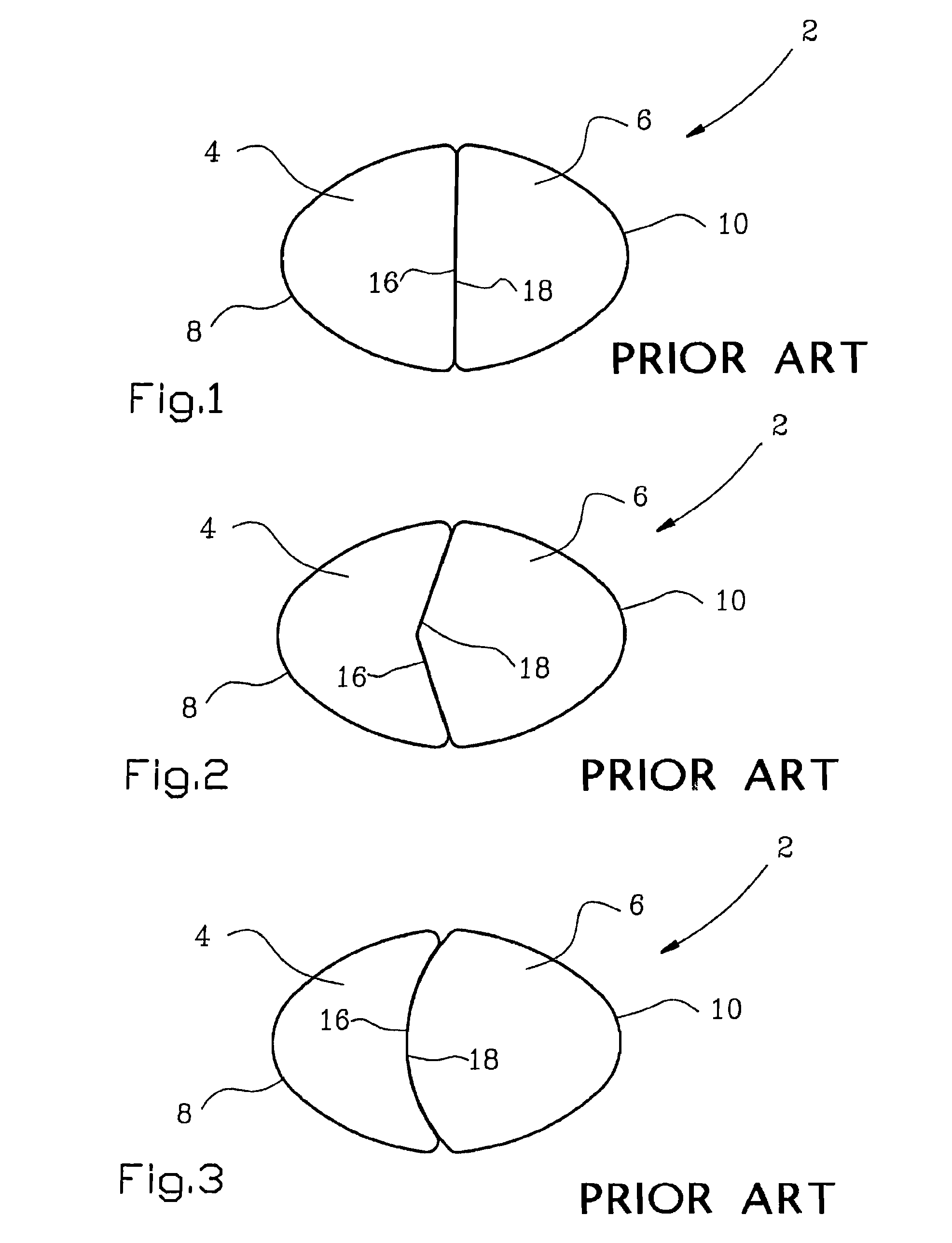
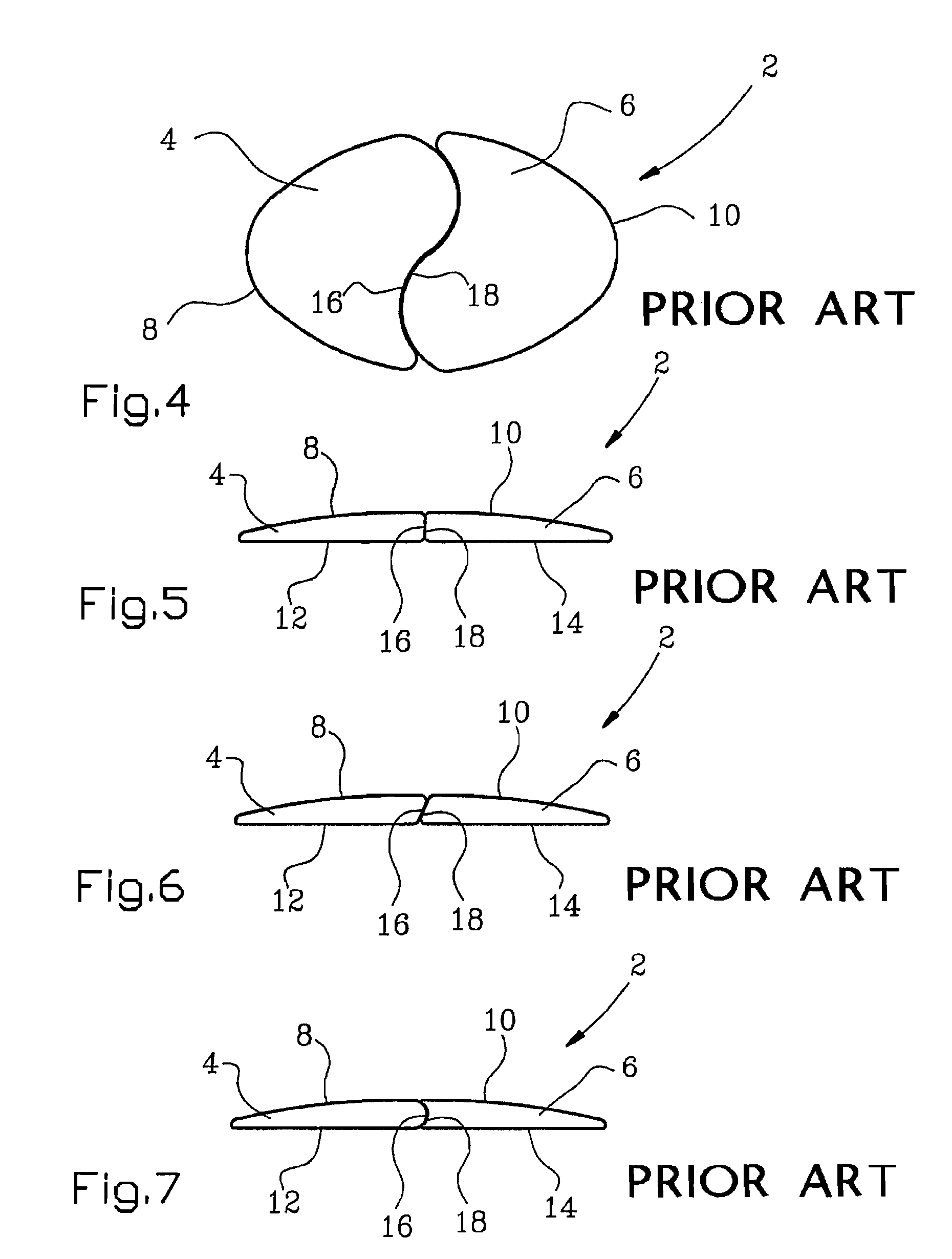
[0114]FIGS. 1-10 disclose pairs 2 of orthodontic retainer elements 4 and 6 according to prior art of Amundsen. Each such retainer element 4, 6 includes an oral surface 8 and 10, respectively; a dental attachment surface 12 and 14, respectively; and an approximal surface 16 and 18, respectively.

[0115]In FIG. 10, an approximal surface 16, 18 of a retainer element 4, 6 is attached on either side of a guide strip 36 according to prior art of Amundsen, and at one end thereof directly opposite to each other. As mentioned above, this attachment constellation of the retainer element 4, 6 to the guide strip 36 may cause some misalignment between the elements 4, 6 as they are released from the guide strip 36 and attached to corresponding teeth. This is a problem that the present invention seeks to remedy.

[0116]FIGS. 11 and 12 show a mounting jig in the form of a rectangular base 24, 124 comprising a dental side 26, 126; an oral side 28, 128; and a perimeter side 30, 130, respectively. Said de...


PUM


Abstract

The invention concerns a mounting device for a pair of orthodontic retainer elements intended for attachment to a pair of adjacent teeth in a dental arch during passive orthodontic treatment. The retainer elements include approximal surfaces formed complementary to each other so as to form contact surfaces capable of stabilizing each other when the pair of retainer elements is attached to the pair of adjacent teeth, thereby also stabilizing the pair of teeth. The mounting device comprises a jig to which the pair of retainer elements is releasably connected and is maintained in a specific spatial relationship, which allows the approximal surfaces to form the stabilizing contact surfaces when mounted on the pair of teeth. The invention also concerns a method of maintaining a correct spatial relationship between the pair of retainer elements, especially when attaching them to the pair of teeth.

Description

BACKGROUND OF THE INVENTION[0001]The present invention concerns a mounting jig for a pair of orthodontic retainer elements. During orthodontic treatment, the pair of retainer elements is intended for retaining, i.e. stabilizing, a pair of adjacent teeth relative to each other in a dental arch of a patient. As such, at least one pair of adjacent teeth may be stabilized in the patient's mandible (lower jaw) and / or maxilla (upper jaw). The purpose of the mounting jig is to maintain mechanically a correct spatial relationship between the two retainer elements in a pair thereof, particularly in the process of attaching the retainer elements to the adjacent teeth of the patient.[0002]The present invention also concerns a method of maintaining a correct spatial relationship between the retainer elements in a pair thereof, particularly in the process of attaching the retainer elements to the adjacent teeth.[0003]Orthodontic treatment generally includes a period of active treatment and a per...

Claims


Application Information

Patent Timeline
Patent Type & Authority Patents(United States)
IPC IPC(8): A61C3/00
CPCA61C7/00A61C7/08
Inventor AMUNDSEN, OLE C.
Owner AMUNDSEN OLE C
Why Eureka
Try Eureka