Antenna device
a technology of an antenna and a range, applied in the direction of anti-theft devices, program control, instruments, etc., can solve the problems of difficult formation of complicated setting of the communication range, and difficulty in forming the communication range with a good accuracy, etc., to achieve good accuracy
- Summary
- Abstract
- Description
- Claims
- Application Information
AI Technical Summary
Benefits of technology
Problems solved by technology
Method used
Image


Examples
first embodiment
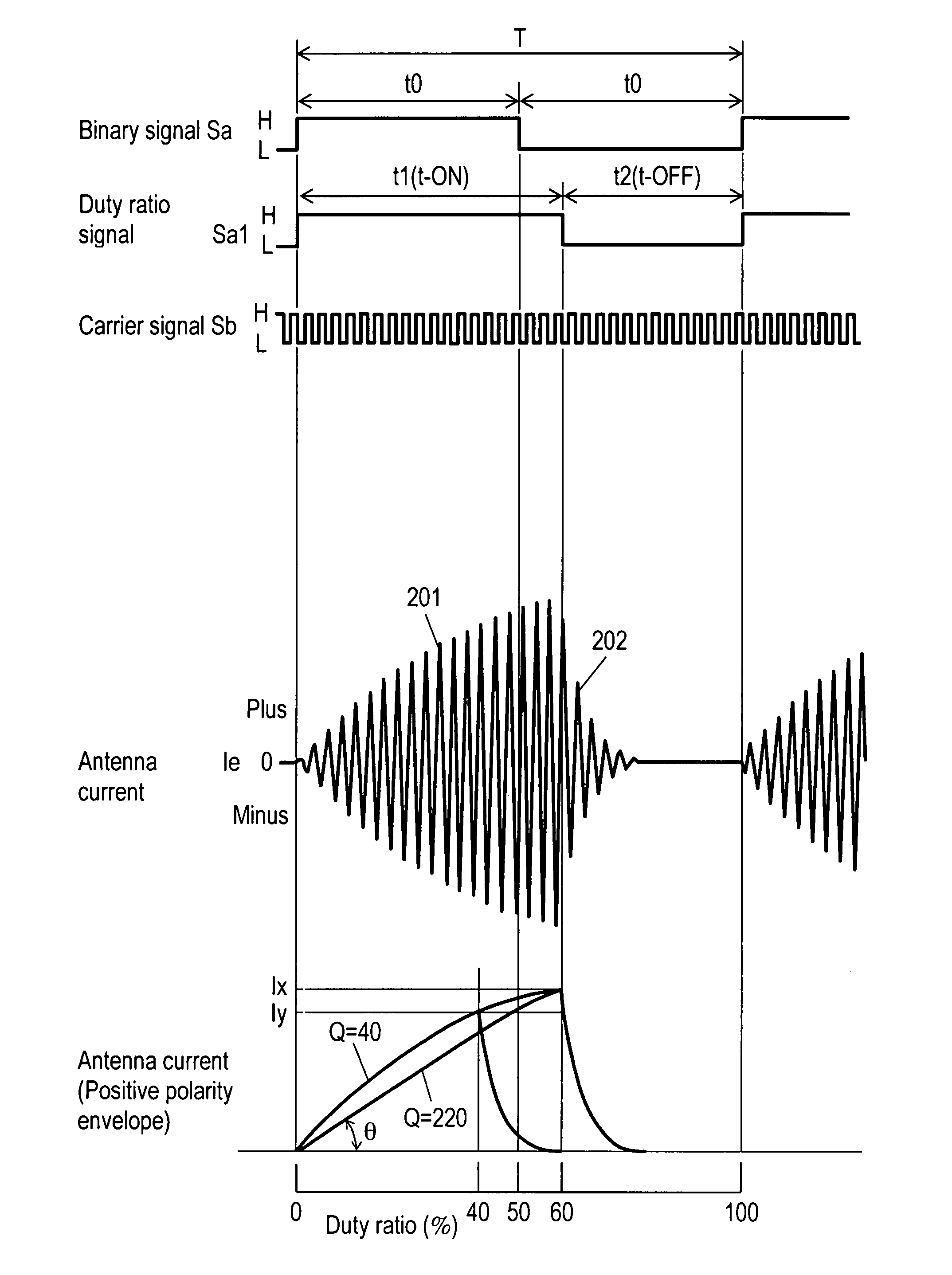
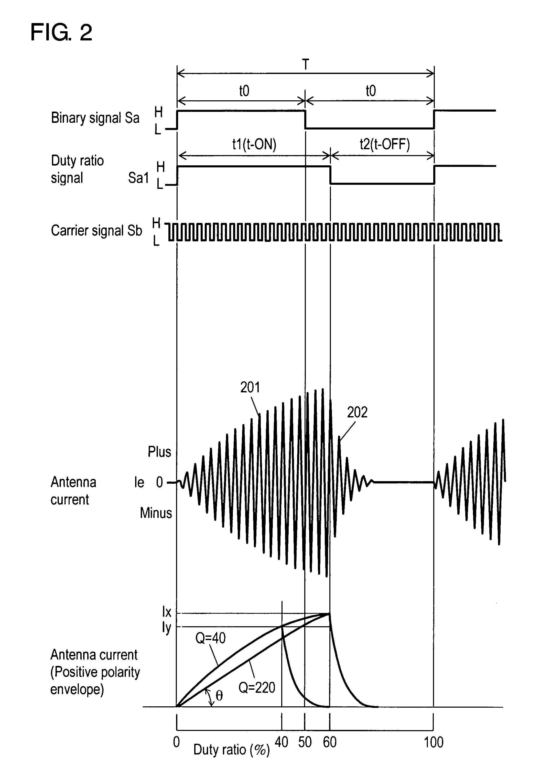
[0040]FIG. 1 is a block diagram of antenna device according a first embodiment of the present invention. FIG. 2 is waveform diagrams demonstrating an operation of antenna device according to the first embodiment of the present invention.
[0041]Referring to FIG. 1, antenna device 10 includes transmitting unit 12 and transmission antenna 5 connected to transmitting unit 12. Transmitting unit 12 includes duty ratio controller 1, driving circuit 4, switching circuit 7, resistance 26, and resistance 6.
[0042]Duty ratio controller 1 includes duty ratio control unit 1a and storage unit 1b. Storage unit 1b stores duty ratio information on a plurality of duty ratios in advance. Duty ratio control unit 1a controls such that binary signal Sa of the duty ratio 50% shown in FIG. 2 becomes desired duty ratio signal Sa1 shown in FIG. 2, according to the duty ratio information selected from storage unit 1b. Binary signal Sa is input from a control unit (not shown) of the in-vehicle device to duty rat...
second embodiment
[0070]In a second embodiment of the present invention, the same reference numerals can be denoted to the same component as in the first embodiment of the present invention and the detailed description will be simplified.
[0071]FIG. 3 is a block diagram of an antenna device according to the second embodiment of the present invention. Transmitting unit 31 further includes current detecting circuit 32 that detects antenna current Ie in addition to elements of transmitting unit 12 of the first embodiment of the present invention.
[0072]Current detecting circuit 32 includes resistance 34, amplifier 36, and low-pass filter 38. Resistance 34 is inserted between third power transistor 23 and GND. Amplifier 36 amplifies the voltage generated in resistance 34 by the flowing of antenna current Ie. Low-pass filter 38 is configured with resistance 38a and capacitor 38b. Low-pass filter 38 smoothes the output signal of amplifier 36. Moreover, antenna device 30 feedbacks analog detecting signal Si t...
third embodiment
[0079]FIG. 4 is a block diagram of an antenna device according to a third embodiment of the present invention. FIG. 5 is waveform diagrams demonstrating an operation of this antenna device.
[0080]FIG. 6 is a block diagram of another antenna device according to the third embodiment of the present invention.
[0081]In the third embodiment of the present invention, the same reference numerals can be denoted to the same component as in the first and second embodiments of the present invention, and the detailed description will be simplified.
[0082]Transmitting unit 120 includes duty ratio controller 1.
[0083]Duty ratio controller 1 has the same components as the duty ratio controller demonstrated in the first and second embodiments of the present invention. In a word, as described in the first embodiment of the present invention, duty ratio controller 1 controls such that binary signal Sa of the duty ratio 50% shown in FIG. 5 becomes desired duty ratio signal Sa1 shown in FIG. 5. Binary sign...
PUM
 Abstract
Description
Claims
Application Information
 - R&D
- Intellectual Property
- Life Sciences
- Materials
- Tech Scout
- Unparalleled Data Quality
- Higher Quality Content
- 60% Fewer Hallucinations
Browse by: Latest US Patents, China's latest patents, Technical Efficacy Thesaurus, Application Domain, Technology Topic, Popular Technical Reports.
© 2025 PatSnap. All rights reserved.Legal|Privacy policy|Modern Slavery Act Transparency Statement|Sitemap|About US| Contact US: help@patsnap.com