
Variable power optical system, imaging lens system and digital apparatus
a lens system and variable power technology, applied in the field of zoom optical system, can solve the problems of limited objects to be photographed, difficult to employ the lens barrel, and insufficient miniaturization of the optical system, and achieve the effect of maximal suppression of moving objects and sufficient correction of magnification chromatic aberration
- Summary
- Abstract
- Description
- Claims
- Application Information
AI Technical Summary
Benefits of technology
Problems solved by technology
Method used
Image

Examples
example 1
[0171]FIG. 6 is a cross-sectional view i.e. an optical path diagram, taken along the optical axis (AX), showing an arrangement of lens groups in a zoom optical system 100A as Example 1. The optical path diagrams in FIG. 6, and FIGS. 7 through 24 to be described later each shows a lens arrangement at the wide angle end (W). Throughout Example 1, and Examples 2 through 18 to be described later, the lens groups include, in this order from the object side in the drawings i.e. the left side in FIG. 6, a first lens group (Gr1) having a negative optical power as a whole, a second lens group (Gr2) having a positive optical power as a whole, and a third lens group (Gr3) having a positive or negative optical power as a whole. In other words, the lens arrangement is a negative dominant arrangement, in which the first lens group closest to the object side has a negative optical power.
[0172]The zoom optical system 100A in Example 1 shown in FIG. 6 has the following lens group arrangement in the ...
example 2
[0192]FIG. 7 is a cross-sectional view, taken along the optical axis (AX), showing an arrangement of lens groups in a zoom optical system 100B as Example 2. The zoom optical system 100B in Example 2 includes, in the order from the object side, a first lens group (Gr1) having a negative optical power, an aperture stop (ST) arranged on the object side of a second lens group (Gr2), the second lens group (Gr2) having a positive optical power as a whole, a third lens group (Gr3) having a positive optical power, and a fourth lens group (Gr4) having a negative optical power. More specifically, the first lens group (Gr1) is constituted of a biconcave negative lens element (L1) and a positive meniscus lens element (L2) convex to the object side in this order from the object side. The second lens group (Gr2) is constituted of a biconvex positive lens element (L3) and a biconcave negative lens element (L4). The third lens group (Gr3) is constituted of a positive meniscus lens element (L5) conv...
example 3
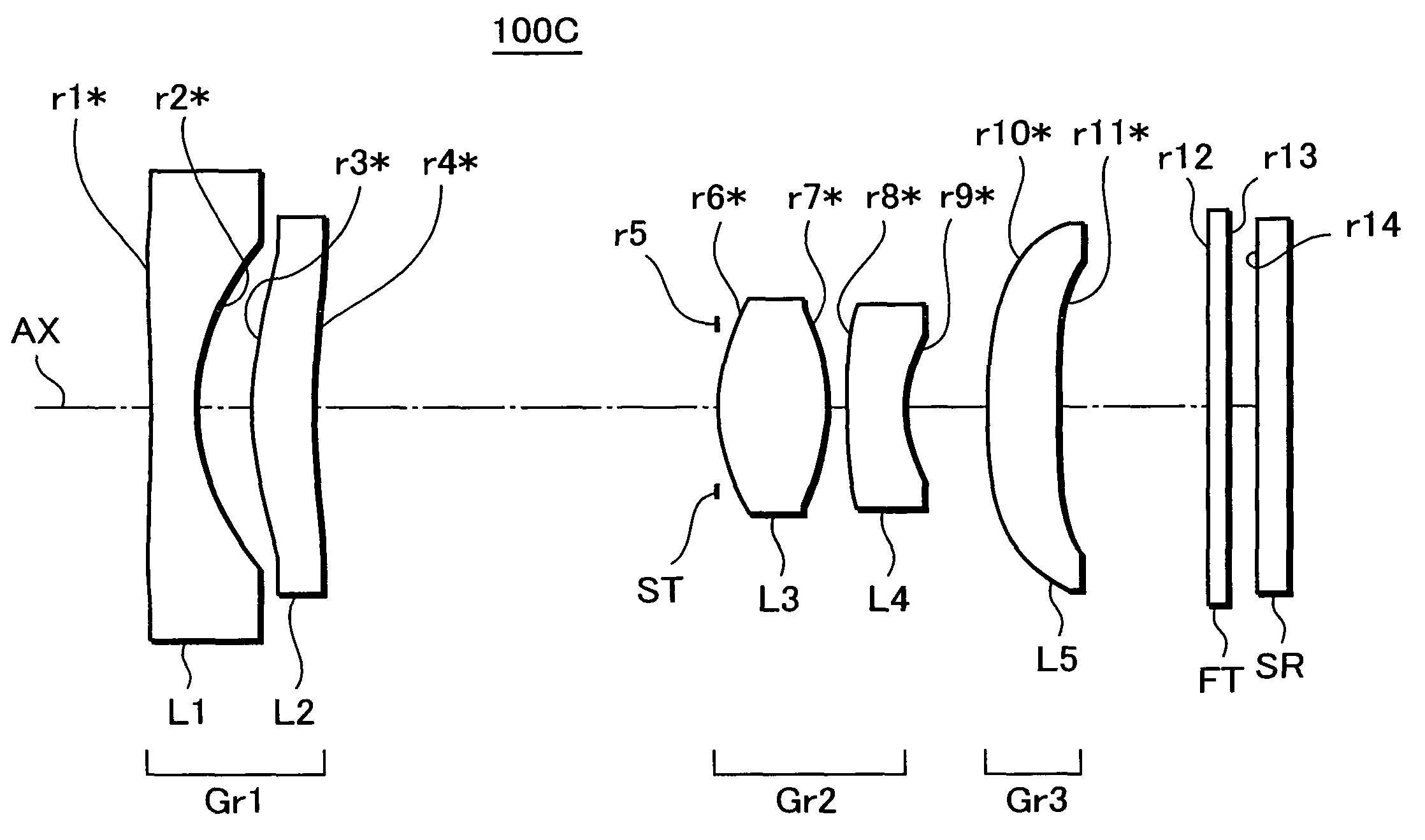
[0197]FIG. 8 is a cross-sectional view, taken along the optical axis (AX), showing an arrangement of lens groups in a zoom optical system 100C as Example 3. The zoom optical system 100C in Example 3 includes, in the order from the object side, a first lens group (Gr1) having a negative optical power as a whole, an aperture stop (ST) arranged on the object side of a second lens group (Gr2), the second lens group (Gr2) having a positive optical power as a whole, and a third lens group (Gr3) having a positive optical power. More specifically, the first lens group (Gr1) is constituted of a biconcave negative lens element (L1) and a positive meniscus lens element (L2) convex to the object side in this order from the object side. The second lens group (Gr2) is constituted of a biconvex positive lens element (L3) and a negative lens element (L4) convex to the object side in this order from the object side. The third lens group (Gr3) is constituted of a positive meniscus lens element (L5) c...
PUM
 Abstract
Description
Claims
Application Information