Optical pick-up apparatus

a technology of optical pickup and optical beam source, which is applied in the field of optical pickup apparatus, can solve the problems of axial chromatic aberration, spherical aberration becoming an important problem, and the increase of the spot diameter, and achieve the effect of suppressing axial chromatic aberration

Inactive Publication Date: 2005-12-22
KONICA CORP
View PDF1 Cites 30 Cited by
  • Summary
  • Abstract
  • Description
  • Claims
  • Application Information

AI Technical Summary

Benefits of technology

[0010] Further, another object of the present invention is to provide an optical pick-up apparatus by which the axial chromatic aberration due to the mode hopping and HFCS (high frequency superimposition) of the semiconduction laser can be effectively corrected, and its objective lens and the beam expander.
[0252] When the magnification is not less than the lower limit of the conditional expression above, the composite optical system can be compact in size, and when it is not more than the upper limit, aberration of the coupling lens turns out to be better.

Problems solved by technology

A problem actualized in the combination of the shortening of the wavelength of the laser and the increase of the NA of the objective lens, is a variation of the spherical aberration of the optical system due to the temperature and humidity change.
Even in a variation of the spherical aberration by the change of the refractive index which is not a problem in the optical system used in the conventional pick-up apparatus, its amount is not negligible in the combination the reduction of the wavelength of the laser and the increase of the NA of the objective lens, and a problem in which the spot diameter is increased, is generated.
Accordingly, in the optical system employing a plastic lens, a spherical aberration becomes an important problem.
Further, another problem in the combination of the shortening of the wavelength of the laser and the increase of the NA of the objective lens, is deviation of a spherical aberration taking place on the objective lens due to the slight deviation of wavelength of the light source.
As a result, the cost of the semiconductor laser will be raised.
Further, another problem in the combination of the shortening of the wavelength of the laser and the increase of the NA of the objective lens, is deviation of a spherical aberration of the optical system due to errors in the thickness of a protective layer (or a transparent substrate) of the optical disk.
Since the spherical aberration caused by the errors in the thickness of the protective layer occurs in proportion to fourth power of numerical aperture of the objective lens, the influence of the errors in the thickness of the protective layer becomes larger as the numerical aperture of the objective lens becomes larger, there my be a fear that recording or reproducing information can not be conducted stably.
Therefore, if the information of CD or DVD is reproduced by the objective lens for use in the next future generation, a large spherical aberration may be occurred.
Accordingly, at least by using the common objective lens, without greatly increasing the cost, and by a compact optical pick-up apparatus, how to record or reproduce the information by suppressing the spherical aberration for the different optical information recording medium including the next generation optical disk, is a problem.
Further, the other problems is a problem of the axial chromatic aberration caused in the objective lens due to minute variations of the wavelength of the laser light source.

Method used


Image

  • Optical pick-up apparatus
  • Optical pick-up apparatus
  • Optical pick-up apparatus

Examples


example 1

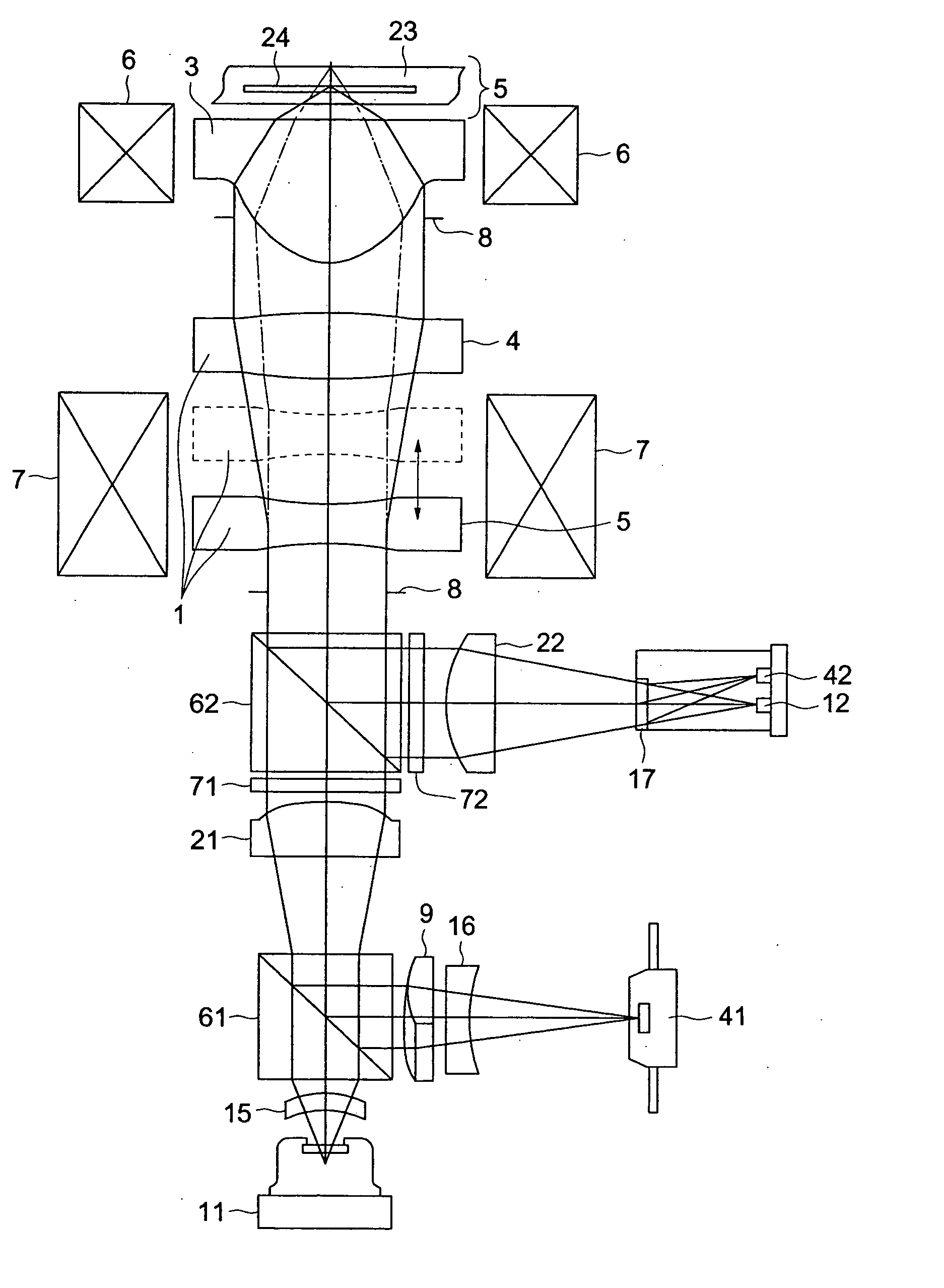
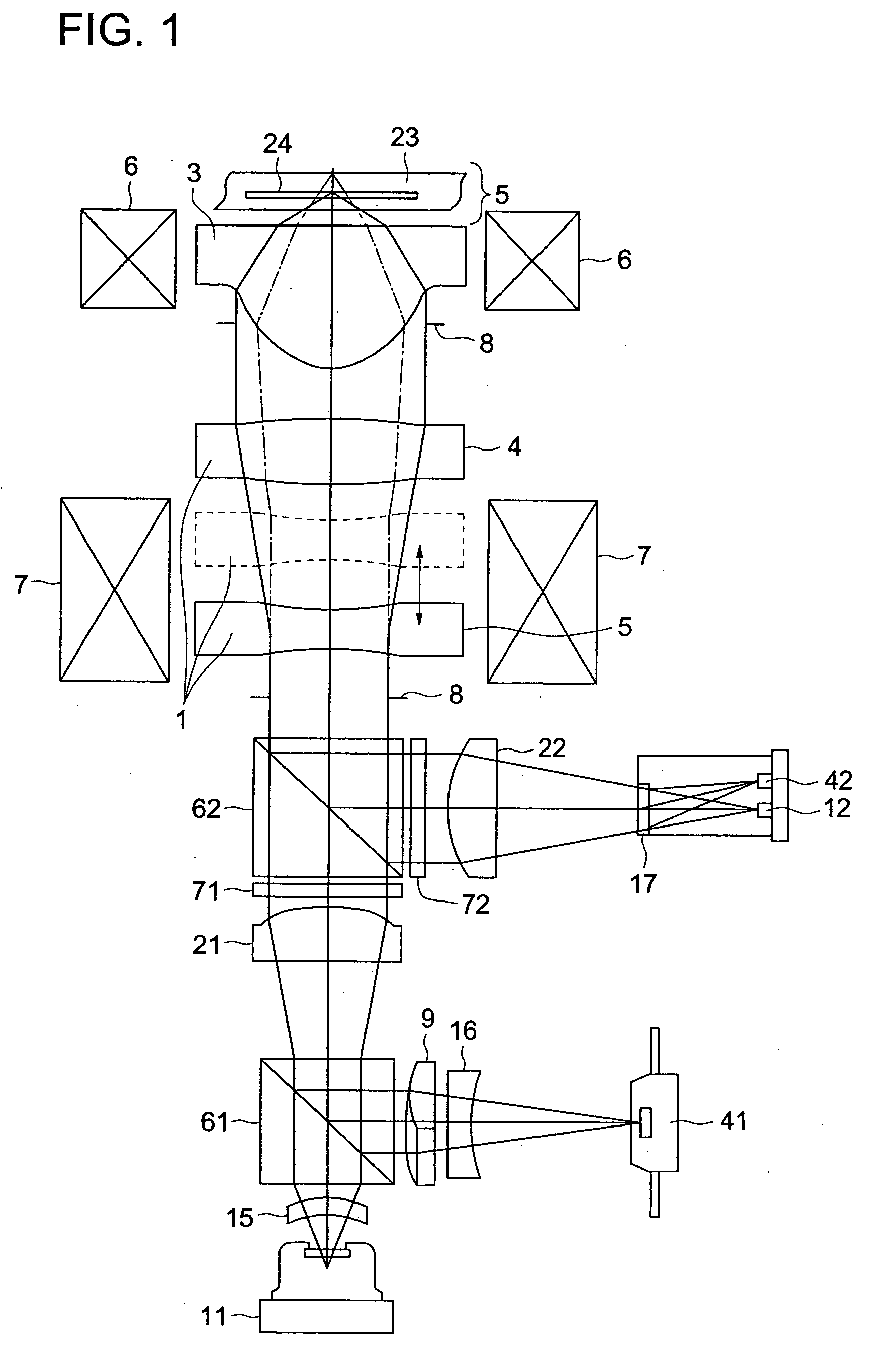
[0430] The data for the optical system composed of the negative lens 5, positive lens 4, and objective lens 3 in the example 1 is shown in Table 1. In this connection, in the data shown hereinafter, the powers of 10 (for example, 2.5×10⁻³) is expressed by using E (for example, 2.5×E-3). Further, the first order light by the diffraction of the diffractive surface expressed by the rotation symmetry polynomial means the light in which an angle of the ray of light changes in the converging direction after the diffraction.

TABLE 1Example 1λ1 405 nmNA 0.85r(mm)d(mm)Nλ1νd1Spherical−604.7110.8001.9140923.82aberration7.5321.0003correction8.1221.2001.5071781.64means−11.1991.0005 (Diaphragm)∞0.0006 (AsphericObjective1.2332.6881.5252456.5  surface 1,lens  diffractive  surface 1)7 (Aspheric−0.9310.334  surface 2)8Transparent∞0.1001.5194930.09substrate∞0.000Aspheric surface 1K−6.8440E−01A4  1.7085E−02A6  2.4417E−03A8  1.4011E−03A10  3.9966E−04A12−2.0375E−04A14  1.8903E−05A16  2.6231E−05A18  2.30...

example 2

[0433] The data relating to the optical system composed of the negative lens 5, positive lens 4 and objective lens 3 in the example 2 is shown in Table 3.

TABLE 3Example 2λ1 405 nmNA 0.85r(mm)d(mm)Nλ1νd1Spherical−6.5510.8001.61949 30.02aberration5.5821.0003correction8.5421.2001.5252456.54means−5.3641.0005 (Diaphragm)∞0.0006 (AsphericObjective1.2332.6881.5252456.5  surface 1,lens  diffractive  surface 1)7 (Aspheric−0.9310.334  surface 2)8Transparent∞0.1001.6194930.09substrate∞0.000Aspheric surface 1K−6.8440E−01A4  1.7085E−02A6  2.4417E−03A8  1.4011E−03A10  3.9966E−04A12−2.0375E−04A14  1.8903E−05A16  2.6231E−05A18  2.3047E−05A20−1.4976E−05Aspheric surface 2K−22.173426A40.345477A6−0.821245A80.890651A10−0.391613A12−0.252257E−03 A14−0.109061E−09 A16−0.166822E−10 A18−0.250470E−11 A20−0.370377E−12 Diffractive surface 1B2−7.0001E−03

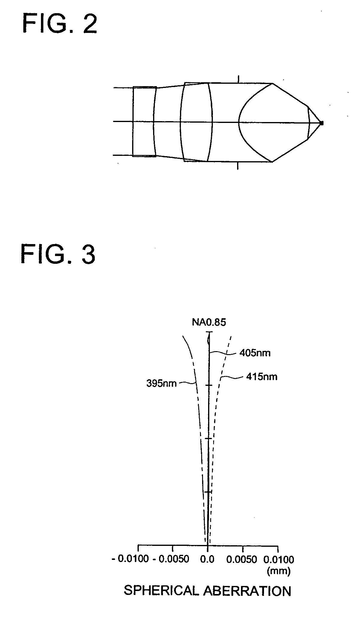
[0434]FIG. 4 is an optical system structural view of the negative lens 5, positive lens 4, and objective lens 3 according to the example 2. FIG. 5 is a spherica...

example 3

[0436] The data relating to the optical system composed of the negative lens 5, positive lens 4 and objective lens 3 in the example 3 is shown in Table 5.

TABLE 5Example 3λ1 405 nmNA 0.85r(mm)d(mm)Nλ1νd1Spherical−20.4860.8001.9140923.82aberration14.7291.0003correction26.2781.2001.5071781.64means−7.0401.0005 (Diaphragm)∞0.0006 (AsphericObjective1.2252.8451.5252456.5  surface 1)lens7 (Aspheric−0.7630.292  surface 2)8Transparent∞0.1001.6194930.09substrate∞0.000Aspheric surface 1K−0.699712A4  0.166009E−01A6  0.209051E−02A8  0.157932E−02A10  0.212509E−03A12−0.344184E−03A14  0.119417E−04A16  0.577745E−04A18  0.409189E−04A20−0.257292E−04Aspheric surface 2K−20.033672A40.331327A6−0.881378A80.965015A10−0.412771A12−0.252257E−03A14−0.110756E−09A16−0.168921E−10A18−0.253030E−11A20−0.370376E−12

[0437]FIG. 6 is an optical system structural view of the negative lens 5, positive lens 4, and objective lens 3 according to the example 3. FIG. 7 is a spherical aberration view according to the objective l...


PUM

PropertyMeasurementUnit
thicknessaaaaaaaaaa
humidityaaaaaaaaaa
wavelengthaaaaaaaaaa

Abstract

An optical pickup apparatus for conducting recording and / or reproducing information of an optical information recording medium, comprises a light source; a converging optical system having an objective lens; and a photo-detector. The converging optical system comprises a plastic lens and a spherical aberration deviation correcting element to correct deviation of a spherical aberration of the converging optical system. A numerical aperature of the objective lens at an image-side is 0.65 or more.

Description

BACKGROUND OF THE INVENTION [0001] The present invention relates to an optical pick-up apparatus, an apparatus for recording / reproducing information of an optical information recording medium, and beam expander, and particularly to an optical pick-up apparatus, objective lens and beam expander, by which variations of the spherical aberration can be effectively corrected in a high density optical information recording medium. [0002] Recently, according to the practical use of a short wavelength red semiconductor laser, the development of a DVD (digital versatile disk) which is a high density optical disk whose size is the almost same as a conventional optical disk, that is, a CD (compact disk) which is an optical information recording medium, and whose capacity is greatly increased, is advanced, and in near future, it is presupposed that a higher density next generation optical disk also appears in the market. In the optical system of the optical information recording and reproducing...

Claims


Application Information

Patent Timeline
Patent Type & Authority Applications(United States)
IPC IPC(8): G02B13/18G02B27/00G02F1/1347G11B7/00G11B7/125G11B7/135
CPCG02B13/18G02B27/0068G02F1/13471G02F2203/18G11B7/1275G11B2007/13727G11B7/1378G11B7/13922G11B7/13925G11B2007/0006G11B2007/0013G11B7/1353G02B13/00G11B7/1374
Inventor KIMURA, TOHRUOTA, KOHEI
Owner KONICA CORP
Why Eureka
Try Eureka