Imaging lens and imaging unit

a technology of imaging lens and imaging unit, which is applied in the field of bright large aperture imaging lens, can solve the problems of difficult to secure the necessary optical performance, difficult to achieve the high resolution performance necessary to increase the aperture, and difficult to correct the on-axial chromatic aberration, etc., to achieve favorable optical performance, optimize the configuration of each lens, and suppress the variation in field curvature

Active Publication Date: 2016-02-25
SONY CORP
View PDF20 Cites 54 Cited by
  • Summary
  • Abstract
  • Description
  • Claims
  • Application Information

AI Technical Summary

Benefits of technology

[0042]Next, functions and effects of the imaging lens according to this embodiment will be described.
[0043]This imaging lens has a six-lens configuration as a whole, and the configuration of each lens is optimized; therefore, it is possible to achieve favorable optical performance corresponding to a small imaging device having a large number of pixels. In particular, by adopting an power arrangement of positive, positive, negative, positive, negative, and negative (or positive) in order from the object side, while a total optical length is suppressed, spherical aberration that is on-axial aberration, coma aberration that is off-axial aberration, and a field curvature that may be an issue when the aperture is increased are corrected in a balanced manner. Moreover, since the surface on the image-side of the sixth lens L6 is an aspherical surface including one or more inflection points in the peripheral portion thereof, light rays are allowed to enter the imaging device at an appropriate angle, and the imaging lens is allowed to correspond to an imaging device having a large number of pixels. In particular, the imaging lens is effective in correction of the field curvature.
[0044]Further, by configuring all of the first to sixth lenses L1 to L6 of lenses made of an inexpensive resin, it is possible to suppress variation in the field curvature which may be an issue when temperature varies, while securing mass productivity.
[0045](Description of Conditional Expressions)
[0046]In the imaging lens according to this embodiment, more favorable performance is allowed to be obtained by optimizing the configuration of each lens so as to satisfy at least one of the following conditional expressions, preferably, a combination of two or more of the following conditional expressions. In particular, it is possible to achieve a small large-aperture imaging lens having favorable optical performance corresponding to the imaging device having a large number of pixels.
[0047]where vd3 is an Abbe number of the third lens L3 at d-line, and vd5 is an Abe number of the fifth lens L5 at d-line.

Problems solved by technology

However, these imaging lenses are optimized with an Fno of about 2.2, and when an aperture of this configuration is increased to an Fno of about 1.6, spherical aberration that is on-axial aberration, coma aberration that is off-axial aberration, and field curvature are insufficient; therefore, it is difficult to secure necessary optical performance.
Moreover, in order to further improve optical performance, it is necessary to further suppress on-axial chromatic aberration; however, it is difficult to correct the on-axial chromatic aberration while suppressing the total optical length in this configuration, and it is also difficult to secure high resolution performance necessary to increase the aperture.

Method used


Image

  • Imaging lens and imaging unit
  • Imaging lens and imaging unit
  • Imaging lens and imaging unit

Examples


numerical example 1

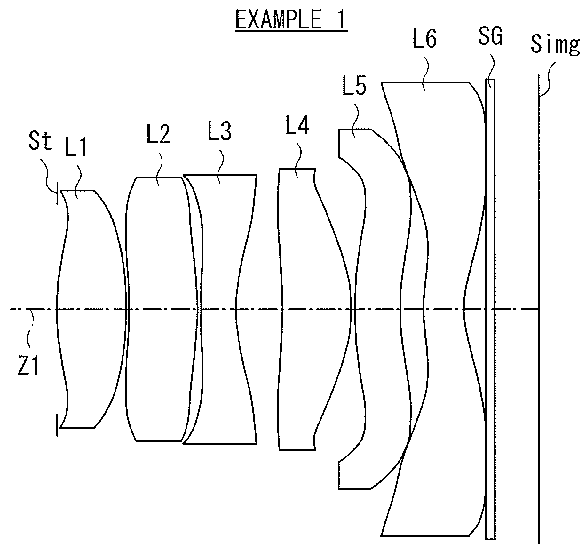
[0081][Table 1] and [Table 2] each illustrate specific lens data corresponding to the imaging lens according to the first configuration example illustrated in FIG. 1. In particular, [Table 1] illustrates basic lens data thereof, and [Table 2] illustrates data related to the aspherical surfaces.

[0082]In this first configuration example, the first lens L1 has a biconvex shape in vicinity of the optical axis. The second lens L2 has a positive meniscus lens that has a convex surface facing toward the image side in vicinity of the optical axis. The third lens L3 is a negative lens having a concave shape on the image side in vicinity of the optical axis. The fourth lens L4 is a positive lens having a convex shape on the image side in vicinity of the optical axis. The fifth lens L5 is a negative meniscus lens that has a concave surface facing toward the image side in vicinity of the optical axis. The sixth lens L6 is a negative meniscus lens that has a concave surface facing toward the ima...

numerical example 2

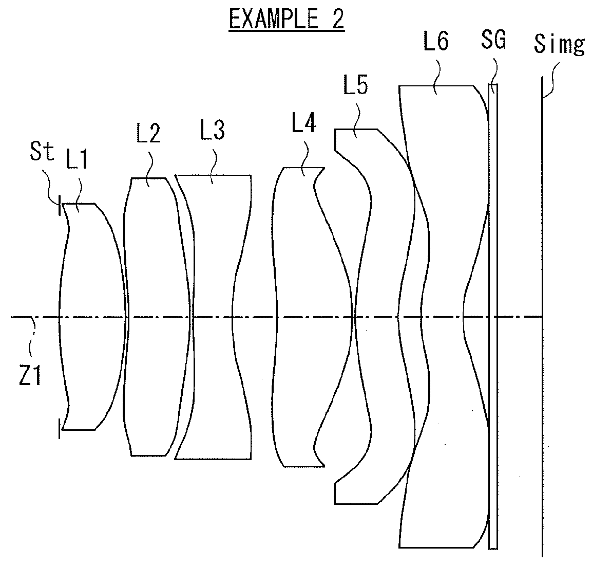
[0084][Table 3] and [Table 4] each illustrate specific lens data corresponding to the imaging lens according to the second configuration example illustrated in FIG. 2. In particular, [Table 3] illustrates basic lens data thereof, and [Table 4] illustrates data related to the aspherical surfaces.

[0085]In this second configuration example, the first lens L1 has a biconvex shape in vicinity of the optical axis. The second lens L2 has a positive meniscus lens that has a convex surface facing toward the image side in vicinity of the optical axis. The third lens L3 is a negative lens having a concave shape on the image side in vicinity of the optical axis. The fourth lens L4 is a positive lens having a convex shape on the image side in vicinity of the optical axis. The fifth lens L5 is a negative meniscus lens that has a concave surface facing toward the image side in vicinity of the optical axis. The sixth lens L6 is a positive meniscus lens that has a concave surface facing toward the i...

numerical example 3

[0087][Table 5] and [Table 6] each illustrate specific lens data corresponding to the imaging lens according to the third configuration example illustrated in FIG. 3. In particular, [Table 5] illustrates basic lens data thereof, and [Table 6] illustrates data related to the aspherical surfaces.

[0088]In this third configuration example, the first lens L1 has a biconvex shape in vicinity of the optical axis. The second lens L2 has a positive meniscus lens that has a convex surface facing toward the image side in vicinity of the optical axis. The third lens L3 is a negative lens having a concave shape on the image side in vicinity of the optical axis. The fourth lens L4 is a positive lens having a convex shape on the image side in vicinity of the optical axis. The fifth lens L5 is a negative meniscus lens that has a concave surface facing toward the image side in vicinity of the optical axis. The sixth lens L6 is a negative meniscus lens that has a concave surface facing toward the ima...


PUM


Abstract

An imaging lens includes: a first lens having positive refractive power; a second lens having positive refractive power; a third lens having negative refractive power; a fourth lens having positive refractive power; a fifth lens having negative refractive power; and a sixth lens having positive or negative refractive power in vicinity of an optical axis, a peripheral portion of a surface on an image side of the sixth lens including one or more inflection points, the first to sixth lenses being provided in order from an object side.

Description

TECHNICAL FIELd[0001]The present disclosure relates to a bright large-aperture imaging lens that is suitable for a small imaging unit using an imaging device such as CCD (Charge Coupled Devices) and CMOS (Complementary Metal Oxide Semiconductor), for example, a digital still camera and a mobile phone provided with a camera, and an imaging unit using such an imaging lens.BACKGROUND ART[0002]A mobile phone provided with a camera and a digital still camera each using a solid-state imaging device such as a CCD and a CMOS are known. In such imaging units, further reduction in size has been desired, and in a lens for shooting to be mounted thereon, further reduction in size and reduction in total length have been desired.[0003]Moreover, recently, in a small imaging unit such as a mobile phone provided with a camera, both reduction in size and an increase in the number of pixels have been achieved, and a model including an imaging device having a large number of pixels, for example, having...

Claims


Application Information

Patent Timeline
Patent Type & Authority Applications(United States)
IPC IPC(8): G02B13/00G02B9/62G02B27/00
CPCG02B13/0045G02B27/0025G02B9/62
Inventor NABETA, KENSHI
Owner SONY CORP
Why Eureka
Try Eureka