Degenerated passive mixer in saw-less receiver

a passive mixer and receiver technology, applied in the direction of substation equipment, radio transmission, electrical equipment, etc., can solve the problems of high quality and high cost, difficult to employ the saw-less passive mixer receiver, and difficult to meet the demanding noise figure (nf) requirements of this topology, so as to reduce the noise in the overall receiver, reduce the noise, and reduce the effect of output impedan

Active Publication Date: 2011-03-01
QUALCOMM INC
View PDF6 Cites 26 Cited by
  • Summary
  • Abstract
  • Description
  • Claims
  • Application Information

AI Technical Summary

Benefits of technology

[0009]In a SAW-less cellular telephone receiver involving a passive mixer, novel degenerative impedance elements (Zdeg) having substantial impedances (for example, twenty ohms or more) are disposed in the incoming RF signal paths between the differential signal output leads of a low-noise amplifier (LNA) and the differential signal input leads of the passive mixer. The LNA has a relatively high output impedance (for example, an output impedance of more than three hundred ohms). The passive mixer has no active gm-cell. The passive mixer in turn outputs down-converted signals to a transimpedance amplifier and baseband filter (TIA) of the receiver. Providing the novel degenerative impedance elements decreases noise in the overall receiver as output from the TIA, with only minimal degradation of other receiver performance characteristics such as linearity and voltage gain. Providing the degenerative impedance elements does not unduly increase noise in the TIA. In one example, in which the impedance of each of the degenerative impedance elements is more than twenty ohms, the TIA has a noise power that is less than twenty percent of the total noise power of the overall receiver. The overall receiver has voltage gain of better than 38 decibels (dB) and a triple beat distortion (TB) magnitude of better than 75 dB.

Problems solved by technology

Other topologies use a high quality and somewhat expensive LNA matching inductor in the matching network between the antenna and LNA.
It is, however, often difficult for this topology to meet demanding noise figure (NF) requirements while still achieving good linearity (e.g., triple beat) performance.
Unfortunately, it is often difficult to employ the SAW-less passive mixer receiver topology of FIG. 1 and also satisfy stringent noise requirements, while at the same time maintaining good linearity and power consumption performance.

Method used


Image

  • Degenerated passive mixer in saw-less receiver
  • Degenerated passive mixer in saw-less receiver
  • Degenerated passive mixer in saw-less receiver

Examples


Embodiment Construction

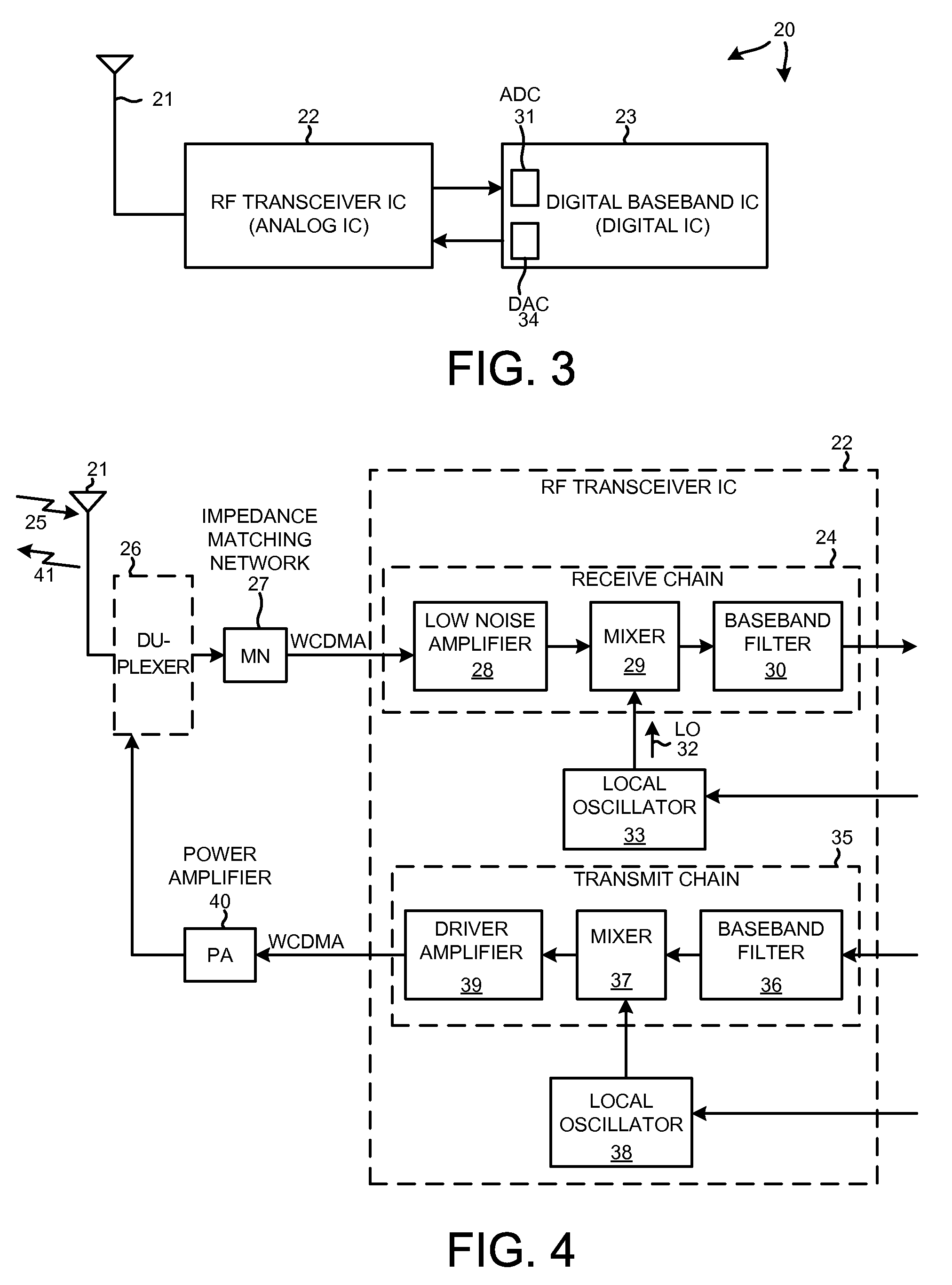
[0023]FIG. 3 is a very simplified high-level block diagram of one particular type of mobile communication device 20 in accordance with one novel aspect. In this example, mobile communication device 20 is a cellular telephone that uses the WCDMA cellular telephone communication protocol. The cellular telephone includes (among several other parts not illustrated) an antenna 21 and two integrated circuits 22 and 23. Integrated circuit 23 is called a “digital baseband integrated circuit” or a “baseband processor integrated circuit”. Integrated circuit 22 is an RF transceiver integrated circuit. RF transceiver integrated circuit 22 is called a “transceiver” because it includes a transmitter as well as a receiver.

[0024]FIG. 4 is a more detailed block diagram of the RF transceiver integrated circuit 22 of FIG. 1. The receiver includes what is called a “receive chain”24 as well as a local oscillator 33. When the cellular telephone is receiving, a high frequency RF signal 25 is received on a...


PUM


Abstract

In a SAW-less receiver involving a passive mixer, novel degenerative impedance elements having substantial impedances are disposed in incoming signal paths between the differential signal output leads of a low-noise amplifier (LNA) and the differential signal input leads of the passive mixer. The passive mixer outputs signals to a transimpedance amplifier and baseband filter (TIA). Providing the novel degenerative impedance elements decreases noise in the overall receiver as output from the TIA, with only minimal degradation of other receiver performance characteristics. In some examples, the passive mixer receives local oscillator signals having duty cycles of substantially less than fifty percent. In some examples, the degenerative impedance elements can have one of several impedances.

Description

PRIORITY CLAIMED[0001]This application claims benefit of U.S. Provisional Application No. 60 / 983,874 titled “DEGENERATED PASSIVE MIXER IN SAW-LESS RECEIVER,” filed Oct. 30, 2007, the entire disclosure of this application being considered part of the disclosure of this application.BACKGROUND INFORMATION[0002]1. Technical Field[0003]The disclosed embodiments relate to low-noise SAW-less receivers having passive mixers.[0004]2. Background Information[0005]There are several different circuit topologies for realizing a cellular telephone receiver. Some topologies involve a surface acoustic-wave (SAW) filter that is disposed in the incoming RF signal path between a low-noise amplifier (LNA) and a mixer. It is desirable to be able to realize a cellular telephone receiver of adequate performance without using the somewhat costly and large SAW device. Other topologies use a high quality and somewhat expensive LNA matching inductor in the matching network between the antenna and LNA. It is al...

Claims


Application Information

Patent Timeline
Patent Type & Authority Patents(United States)
IPC IPC(8): H04B7/00H04B1/16
CPCH04B1/30H04B1/18
Inventor TASIC, ALEKSANDARDENG, JUNXIONGKIM, NAMSOO
Owner QUALCOMM INC
Why Eureka
Try Eureka