Manifold flange

a manifold flange and flange technology, applied in the field of manifold flanges, can solve the problems of cumbersome installation and manufacture of manifold flanges with individual flanges, and achieve the effect of easy handling, fast and reliable installation

Inactive Publication Date: 2011-04-19
TENNECO GMBH
View PDF21 Cites 10 Cited by
  • Summary
  • Abstract
  • Description
  • Claims
  • Application Information

AI Technical Summary

Benefits of technology

[0008]It is therefore an object of the present invention to provide manifold flanges for mounting on the cylinder head of internal combustion engines such that they can be handled and installed easily, quickly and reliably, without losing the desired properties for compensating differences in thermal expansion.
[0010]The present invention is based on the principle of connecting the individual flanges by expansion arches, which yield elastically to the motions of thermal expansion while still allowing handling comparable to a conventional sheet-metal flange. Measures for preventing interchange of the individual flanges are totally eliminated.

Problems solved by technology

However, manufacture and installation of manifold flanges with individual flanges is very cumbersome.
This is unsatisfactory.

Method used


Image

  • Manifold flange
  • Manifold flange
  • Manifold flange

Examples


Embodiment Construction

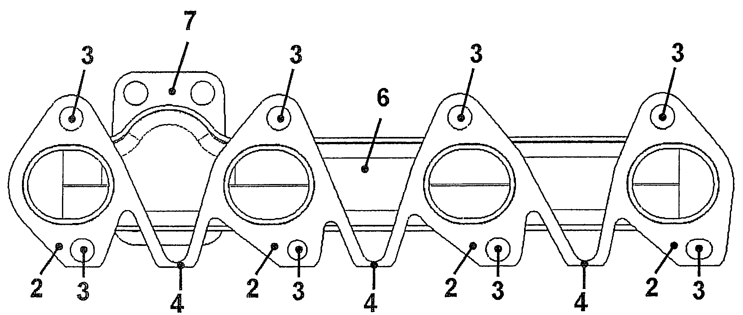
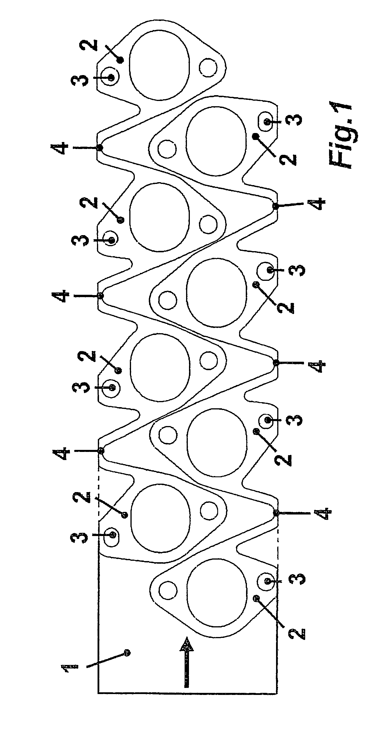
[0017]FIG. 1 shows a metal sheet 1, for example drawn from a coil, out of which are stamped two sets of individual flanges 2 with fastening openings 3. The individual flanges 2 are offset relative to one another for optimization of cuttings.

[0018]Adjacent individual flanges 2 of each set are joined together as one piece by an expansion arch 4. These expansion arches 4 are dimensioned such that they are stable enough to allow convenient and reliable handling of the complete set of individual flanges 2 and arches 4, but are also thin and elastic enough to permit movements of thermal expansion during operation of the internal combustion engine.

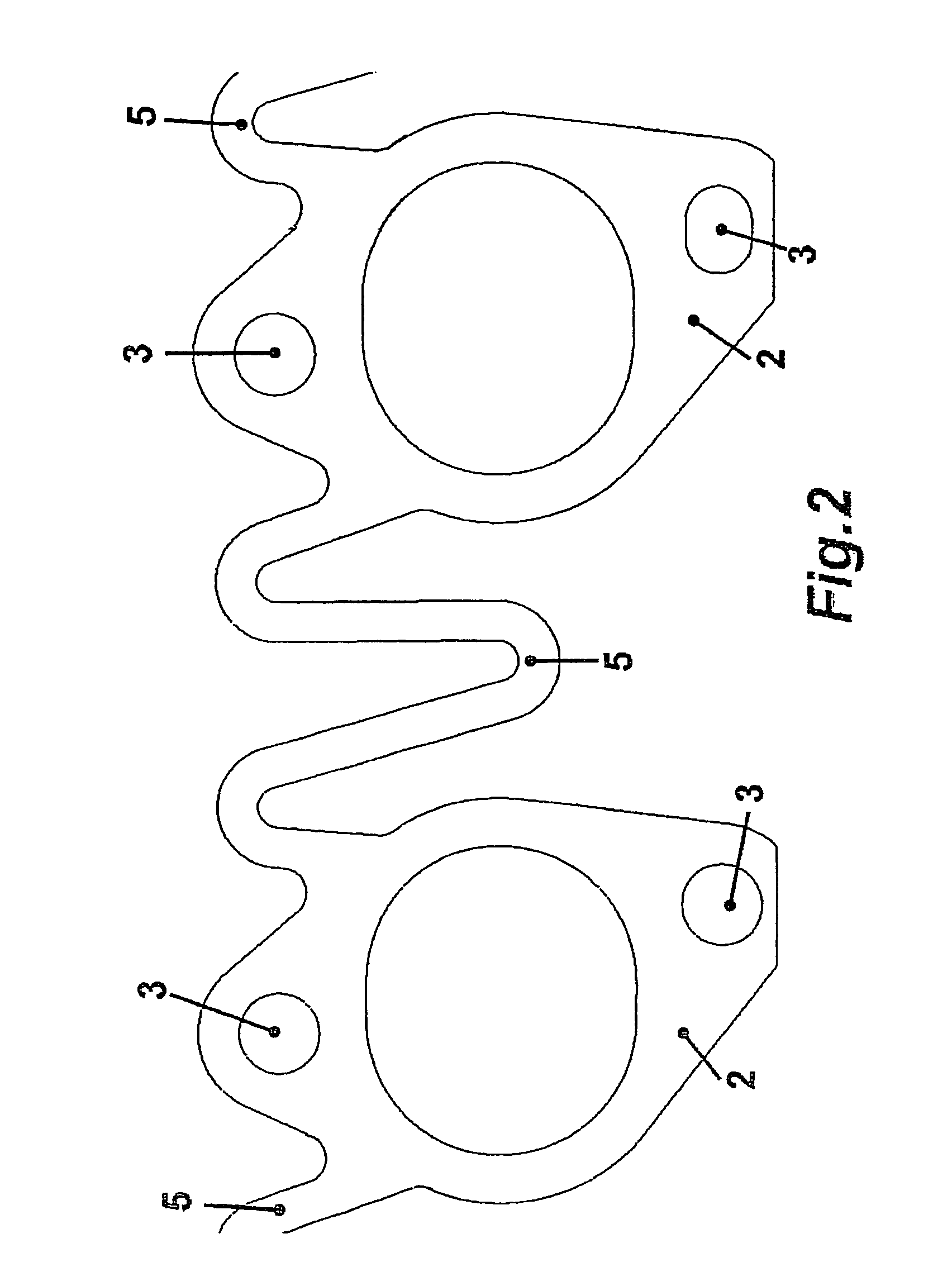
[0019]FIG. 2 shows an alternative embodiment. In this example, the expansion arches 5 are considerably longer in design in order to improve the elastic characteristics. In any event, however, this embodiment also ensures that the complete set of individual flanges 2 and expansion arches 5 can be handled without problem in the manufacturing plant ...


PUM


Abstract

A manifold for mounting on the cylinder head of internal combustion engines includes a manifold housing, a pipe connecting flange, and, for each cylinder, an individual flange with a fastener. To make handling easier, adjacent individual flanges are joined by an expansion arch.

Description

[0001]This nonprovisional application claims priority under 35 U.S.C. §119(a) to German Patent Application No. DE 202006018649, which was filed in Germany on Dec. 9, 2006, and which is herein incorporated by reference.BACKGROUND OF THE INVENTION[0002]1. Field of the Invention[0003]The present invention relates to manifold flanges for mounting on a cylinder head of internal combustion engines, comprising a manifold housing, a pipe connecting flange, and, for each cylinder, an individual flange with fastening means.[0004]2. Description of the Background Art[0005]Manifold flanges for attaching to the cylinder head of internal combustion engines include a manifold housing, which directs hot exhaust gases emerging from the cylinders to a pipe connecting flange where additional exhaust gas treatment elements are fastened. The fastening of the manifold flange to the cylinder head takes place with the aid of flanges, which are installed with the aid of stud bolts and nuts, or with the aid o...

Claims


Application Information

Patent Timeline
Patent Type & Authority Patents(United States)
IPC IPC(8): F01N1/00F16L39/00F01N13/10
CPCF01N13/10
Inventor GEMINN, MARKUS
Owner TENNECO GMBH
Why Eureka
Try Eureka