Check patentability & draft patents in minutes with Patsnap Eureka AI!

Image projection apparatus and image projection system having beam deflection section

a technology of projection apparatus and projection system, which is applied in the field of projection image projector, can solve the problems of speck noise, project image look glaring or too dark or too bright locally, and achieve the effect of improving the quality of the projected imag

Inactive Publication Date: 2011-07-05
PANASONIC CORP
View PDF13 Cites 10 Cited by
  • Summary
  • Abstract
  • Description
  • Claims
  • Application Information

AI Technical Summary

Benefits of technology

The solution effectively reduces speckle noise by averaging noise patterns across frames, enhancing image quality and allowing for a smaller, portable projector without the need for a dedicated screen, as speckle noise is minimized and image quality is improved.

Problems solved by technology

It is known that in presenting an image by projecting coherent light such as a laser beam onto a screen, the laser beams reflected from the projection plane would interfere with each other, thus producing speckle noise that would make the projected image look glaring or too dark or too bright locally.
In this manner, the image comes to have some portions with excessively high luminances and some portions with excessively low luminances, thus producing speckle noise and debasing the quality of the image projected.

Method used


Image

  • Image projection apparatus and image projection system having beam deflection section
  • Image projection apparatus and image projection system having beam deflection section
  • Image projection apparatus and image projection system having beam deflection section

Examples


Embodiment Construction

[0057]Hereinafter, a preferred embodiment of an image projector according to the present invention will be described with reference to the accompanying drawings.

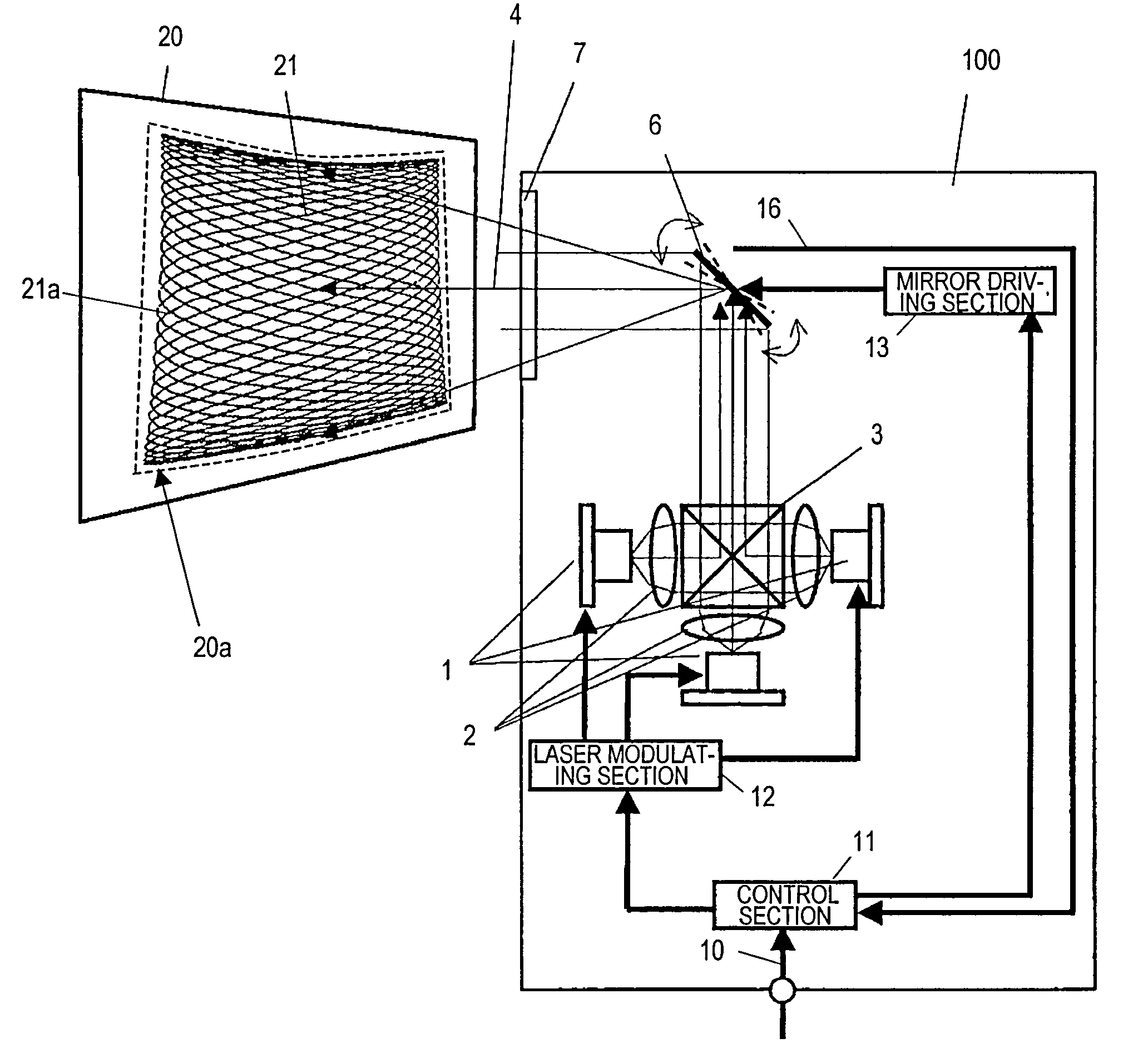
[0058]FIG. 1 is a block diagram showing an arrangement for an image projector 100, which includes a light source 1 and a beam deflection section 6.

[0059]If the image projector 100 is designed to project a color image, the light source 1 preferably includes three light source units that radiate laser beams in the three primary colors of R, G and B, respectively. The laser beams that have been emitted from those three light source units of the light source 1 are converged by their associated collimator lenses 2 and then combined together by the dichroic prism 3, thereby forming a single laser beam 4. The laser beam 4 is deflected two-dimensionally by the beam deflection section 6 and then projected onto a screen 20 through an aperture 7.

[0060]To present an image on the screen 20 by projecting the laser beam 4 onto the screen 2...


PUM


Abstract

An image projector according to the present invention includes a light source for emitting a laser beam, of which the intensity has been modulated in accordance with a modulation signal representing an image to be projected, and a beam deflection section for deflecting the laser beam two-dimensionally such that the image is produced by repeatedly scanning a screen with the laser beam in a predetermined pattern. The predetermined pattern has a repetitive frequency that is lower than a frame rate of the image.

Description

TECHNICAL FIELD[0001]The present invention relates to a projection image projector for presenting image information on a screen by projecting coherent light such as a laser beam thereto.BACKGROUND ART[0002]Some people proposed that a laser diode be used as a light source for an image projector (which is often simply called a “projector”) that is designed to project an image onto a screen. A laser diode can emit light with higher color purity than an incandescent lamp for use in a conventional image projector. That is why it is expected that the image projected would have increased color reproducibility with the use of a laser diode.[0003]Also, if a semiconductor laser diode is used, then a dichroic mirror, which is needed as a spectral element for a conventional incandescent lamp, and other optical elements can be omitted, thus simplifying and downsizing the structure of the optical system and increasing the optical efficiency. For that reason, it is expected that a smaller power-sa...

Claims


Application Information

Patent Timeline
Patent Type & Authority Patents(United States)
IPC IPC(8): G03B21/28
CPCG02B26/0841G02B26/101G03B21/00G09G3/02H04N9/3129G03B21/005
Inventor KUROZUKA, AKIRATOMITA, HIRONORI
Owner PANASONIC CORP
Features
  • R&D
  • Intellectual Property
  • Life Sciences
  • Materials
  • Tech Scout
  • Unparalleled Data Quality
  • Higher Quality Content
  • 60% Fewer Hallucinations
Learn More