Low-drag swept wings

a technology of swept wings and wing configurations, applied in the direction of wings, all-wing aircraft, wing adjustments, etc., can solve the problems of reducing the thickness ratio of aerofoils, affecting the flight path of aircraft, and affecting the flight path, so as to achieve the effect of low drag, increased and decreased angle of attack, and high thickness ratio

Active Publication Date: 2012-02-14
ISRAEL AEROSPACE IND
View PDF5 Cites 4 Cited by
  • Summary
  • Abstract
  • Description
  • Claims
  • Application Information

AI Technical Summary

Benefits of technology

[0013]The aerofoil may further comprise a protection region on a suction surface of said aerofoil and joined to said leading edge downstream of said leading edge, wherein said protection region is configured for preventing or minimizing fast flow acceleration at the leading edge and formation of a sharp suction peak with increasing angle of attack for the aerofoil. Optionally, the protection zone extends downstream of said leading edge by about 30° with respect to a center of said curvature.
[0045]For design work on specific swept wing configurations, the AL-limit can be adjusted to the actual CF-limit, resulting in perhaps more moderate values of leading edge radius and compatible combined laminarization limits with respect to all types of instabilities of laminar boundary layers.

Problems solved by technology

These instabilities may produce premature transition to turbulent flow at the forward portion of the wing sections.
While some conventional NACA aerofoils comprise small leading edge radii that could be advantageous for prevention of attachment line transition when used for swept wings, these aerofoils also have reduced thickness ratio, which in turn provides relatively inferior lift-carrying capabilities.
However, for practical applications in which thick wing sections are of interest, because of physical space requirements for internal installations and storing wing internal fuel for example, aerofoils having high thickness ratio are conventionally provided with a relatively large leading edge radius, which is in conflict with principles of wing laminarization with respect to attachment line transition, if such aerofoils are used for swept wings, particularly at high Reynolds numbers.

Method used


Image

  • Low-drag swept wings
  • Low-drag swept wings
  • Low-drag swept wings

Examples


Embodiment Construction

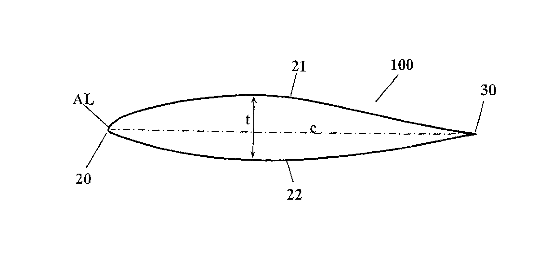
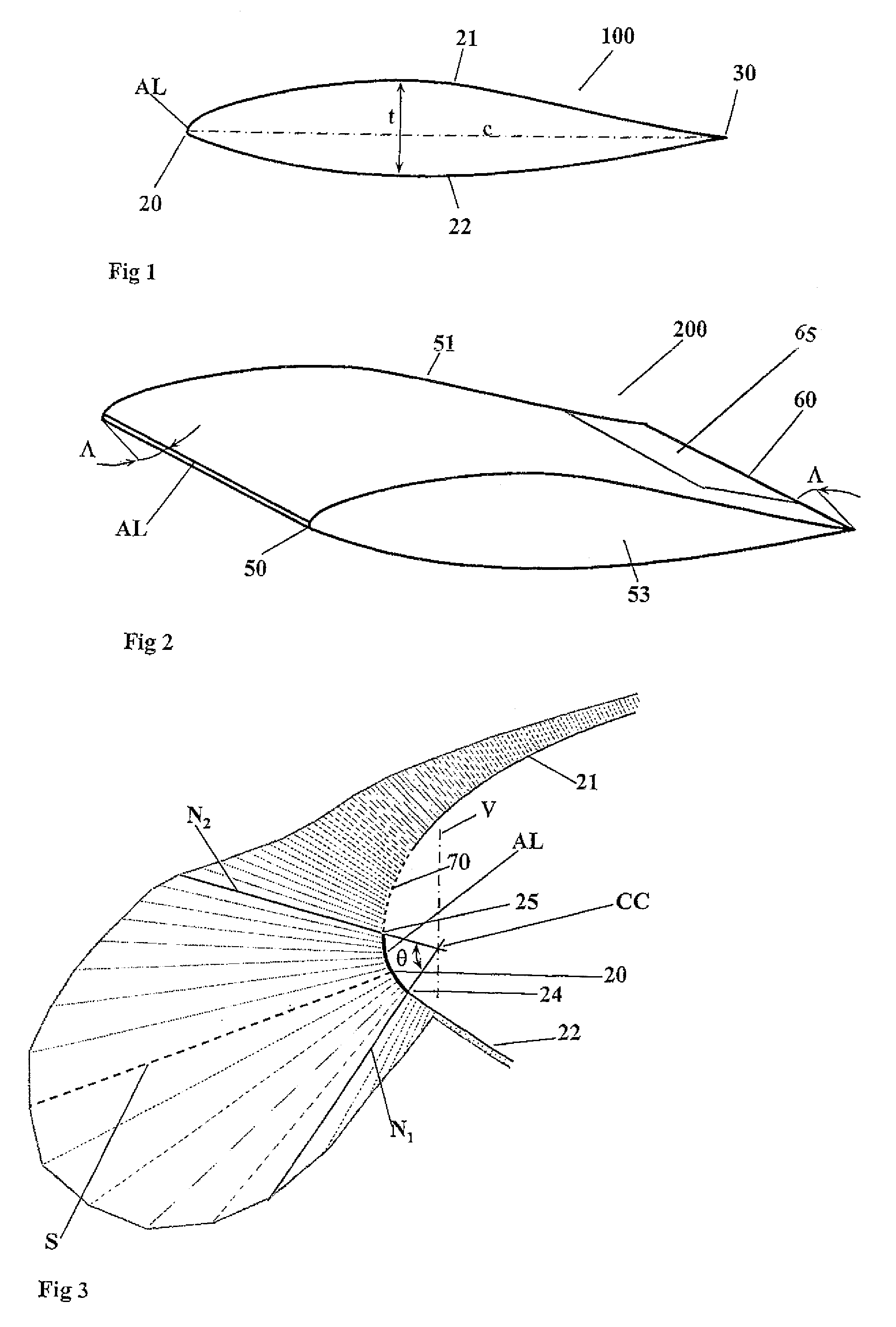
[0086]According to a first embodiment of the invention, and referring to FIG. 1, a Swept Natural Laminar Flow aerofoil (also referred to herein as an SNLF-type aerofoil) is provided, generally designated 100, comprising leading edge 20, suction surface 21, pressure surface 22, and trailing end 30, and the aerofoil 100 also defines a chord c and maximum thickness t.

[0087]Aerofoil 100 may be provided for any suitable subsonic or transonic swept wings, for example high lift wings of an aircraft, in particular fixed wing aircraft (including variable geometry winged aircraft, including for example “swing winged” aircraft). For the purpose of example, such an aircraft is described herein as a fixed-wing aircraft, comprising a regular subsonic / transonic configuration, having a fuselage section, main wings, tailplane, vertical stabilizer, and a propulsion system, but may instead include, mutatis mutandis, any other type of aircraft, for example: flying wing configurations, rotor-wing aircra...


PUM


Abstract

The invention relates to an aircraft, and a method for operating an aircraft, the aircraft having a longitudinally unstable configuration and swept wings, the swept wings being based on aerofoils having a leading edge and configured for preventing attachment line transition in conditions of laminar flow over the swept wing for at least a predetermined first range of lift coefficients at a second range of Reynolds numbers. The invention also relates to an aerofoil, and to a method for providing an aerofoil, the airfoil being configured for a thick-sectioned subsonic / transonic swept wing, having a curved leading edge, a trailing edge, a thickness dimension and a chord dimension, wherein the leading edge comprises a leading edge curvature associated with a leading edge radius that is configured for preventing attachment line transition in conditions of laminar flow over the swept wing.

Description

[0001]This application claims the benefit of prior U.S. provisional patent application No. 60 / 879,028, filed on Jan. 8, 2007, the contents of which are hereby incorporated by reference in their entirety.FIELD OF THE INVENTION[0002]This invention relates to aircraft configurations and to wing configurations and aerofoil sections for aircraft.BACKGROUND OF THE INVENTION[0003]Laminarization of lifting surfaces, such as for example the wings of an aircraft, may provide reduced parasite drag of the wings and improvement of aerodynamic efficiency of the aircraft, wherein skin friction at laminar flow is much less than for fully turbulent flow for a given Reynolds number (Refs. 1-3). Extended laminarization, particularly of relatively thick wing sections at relatively high Reynolds numbers may be attributed to the favorable accelerating pressure gradient at the forward portion of the aerofoil and its beneficial effect on stability of the laminar boundary layer. At the lift coefficients ass...

Claims


Application Information

Patent Timeline
Patent Type & Authority Patents(United States)
IPC IPC(8): B64C3/14
CPCB64C3/14B64C2003/146Y02T50/12Y02T50/10
Inventor SHEPSHELOVICH, MICHAELSZNABEL, ANTHONY-SAMUELLEVY, DAVID-ELI
Owner ISRAEL AEROSPACE IND
Why Eureka
Try Eureka