In-ear monitor with concentric sound bore configuration

a technology of concentric sound bore and in-ear monitor, which is applied in the direction of frequency/directions obtaining arrangements, earpiece/earphone attachments, electrical equipment, etc., can solve the problems of only finding the most common, the degree of customization, and the cost of armature receivers

Active Publication Date: 2012-02-14
LOGITECH EURO SA
View PDF25 Cites 22 Cited by
  • Summary
  • Abstract
  • Description
  • Claims
  • Application Information

AI Technical Summary

Problems solved by technology

Generic earpieces may include a removable and replaceable eartip sleeve that provides a limited degree of customization.
Due to the inherent cost of armature receivers, however, they are typically only found in hearing aids and high-end in-ear monitors.
Diaphragm receivers, due to the use of moving-coil speakers, suffer from several limitations.
First, because of the size of the diaphragm assembly, a typical earpiece is limited to a single diaphragm.
This limitation precludes achieving optimal frequency response (i.e., a flat or neutral response) through the inclusion of multiple diaphragms.
Second, diaphragm-based monitors have significant frequency roll off above 4 kHz.
As the desired upper limit for the frequency response of a high-fidelity monitor is at least 15 kHz, diaphragm-based monitors cannot achieve the desired upper frequency response while still providing accurate low frequency response.
A single armature is capable of accurately reproducing low-frequency audio or high-frequency audio, but incapable of providing high-fidelity performance across all frequencies.

Method used


Image

  • In-ear monitor with concentric sound bore configuration
  • In-ear monitor with concentric sound bore configuration
  • In-ear monitor with concentric sound bore configuration

Examples


Embodiment Construction

[0035]In the following text, the terms “in-ear monitor”, “IEM”, “canal phone”, “earbud” and “earphone” may be used interchangeably. Similarly, the terms “custom” earphone, “custom fit” earphone and “molded” earphone may be used interchangeably and refer to an IEM that is molded to fit within the ear of a specific user. Similarly, the terms “sound delivery tube”, “sound delivery bore” and “sound bore” may be used interchangeably. Unless otherwise noted, the term “driver” as used herein refers to either an armature driver or a diaphragm driver. It should be understood that identical element symbols used on multiple figures refer to the same component, or components of equal functionality. Additionally, the accompanying figures are only meant to illustrate, not limit, the scope of the invention and should not be considered to be to scale.

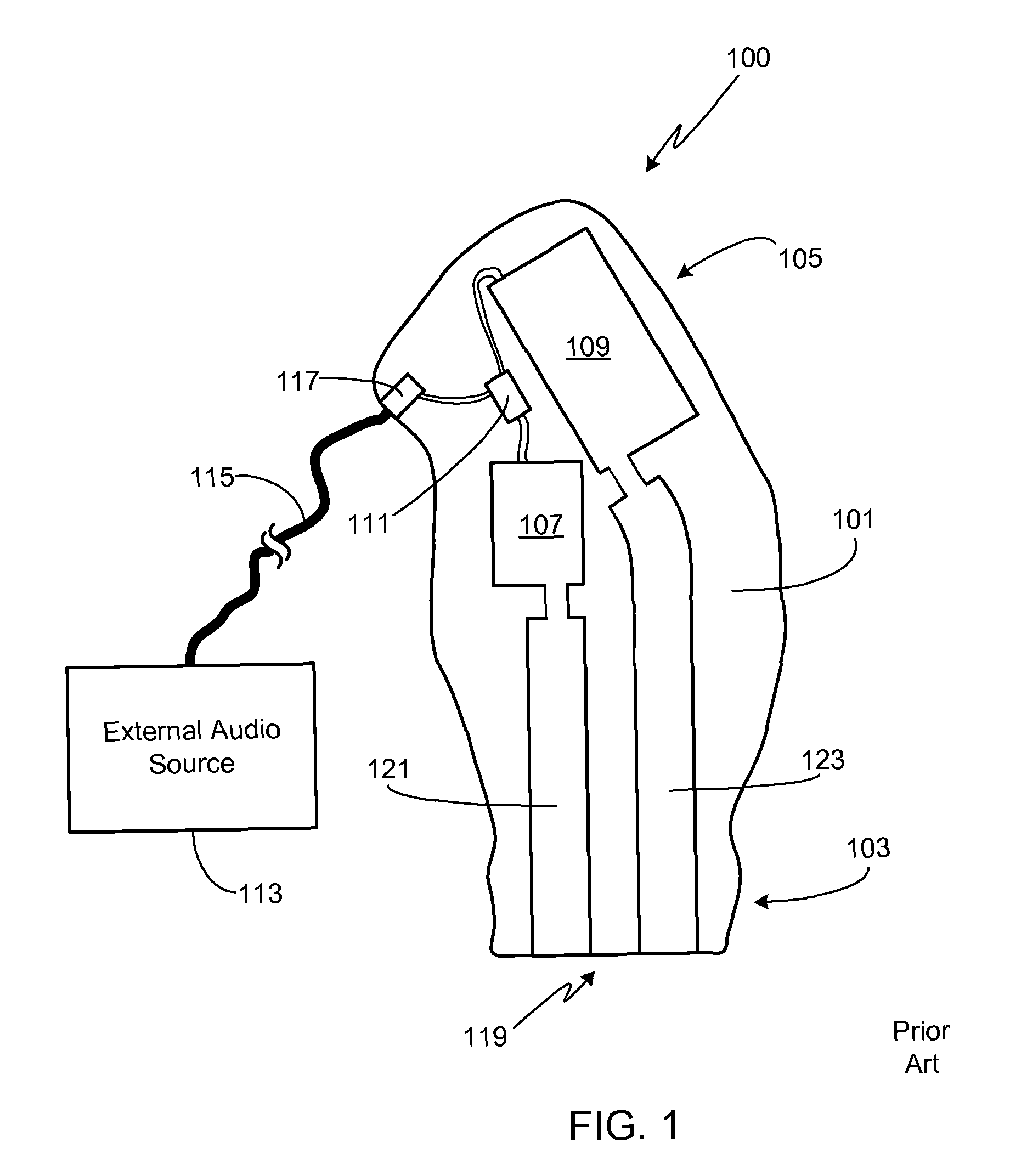
[0036]FIG. 1 illustrates the primary elements of a custom fit in-ear monitor 100 according to the prior art. Being a custom fit IEM, enclosure 101 of ...


PUM


Abstract

A multi-driver, in-ear monitor is provided that is coupleable to an external audio source, for example via a source input cable or a wireless receiver. A circuit, for example comprising a passive or active crossover circuit, receives the electrical signal from the external audio source and provides separate input signals to the drivers contained within the in-ear monitor. A plurality of sound delivery tubes acoustically couple the audio output from each of the drivers to the acoustic output surface of the in-ear monitor. The in-ear monitor may be configured as a custom fit IEM or configured to accept a removable eartip. The plurality of sound delivery tubes may be comprised of a pair of concentric tubes; a pair of concentric tubes and a discrete tube; or three concentric tubes.

Description

CROSS-REFERENCE TO RELATED APPLICATION[0001]This application claims the benefit of the filing date of U.S. Provisional Patent Application Ser. No. 61 / 276,172, filed Sep. 8, 2009, and the benefit of the filing date of U.S. Provisional Patent Application Ser. No. 61 / 281,645, filed Nov. 19, 2009, the disclosures of which are incorporated herein by reference for any and all purposes.FIELD OF THE INVENTION[0002]The present invention relates generally to audio monitors and, more particularly, to an in-ear monitor with multiple sound bores optimized for a multi-driver configuration.BACKGROUND OF THE INVENTION[0003]In-ear monitors, also referred to as canal phones and stereo earphones, are commonly used to listen to both recorded and live music. A typical recorded music application would involve plugging the monitor into a music player such as a CD player, flash or hard drive based MP3 player, home stereo, or similar device using the device's headphone socket. Alternately, the monitor can b...

Claims


Application Information

Patent Timeline
Patent Type & Authority Patents(United States)
IPC IPC(8): H04R25/00
CPCH04R1/1016H04R1/26
Inventor SAGGIO, JR., JOSEPH A.DYER, MEDFORD ALAN
Owner LOGITECH EURO SA
Why Eureka
Try Eureka