Driving method, driving circuit, electro-optical device, and electronic apparatus

a driving circuit and driving circuit technology, applied in the direction of electric digital data processing, instruments, computing, etc., can solve the problems of insufficient response state/behavior of the liquid crystal, the typical field-sequential display is susceptible to color mixture, and the response time of the liquid crystal is relatively long. , the response time of the liquid crystal is relatively long, and the response of the liquid crystal is relatively slow

Inactive Publication Date: 2012-05-15
SEIKO EPSON CORP
View PDF12 Cites 0 Cited by
  • Summary
  • Abstract
  • Description
  • Claims
  • Application Information

AI Technical Summary

Benefits of technology

[0028]As explained above, in the preferred method for driving a display device according to the first aspect of the invention, display data is converted for each of a plurality of fields; and therefore, it is possible to display images having actual brightness and / or color close to desired brightness and / or color at the display area of a display device. More specifically, it is possible to avoid low brightness because of the delayed response of the liquid crystal. In addition, it is further possible to avoid failure in representing a correct color. The advantageous effects of the method for driving a display device according to the first aspect of the invention described above are more remarkable if the response time of the liquid crystal is longer.
[0029]In this respect, in the preferred method for driving a display device according to the first aspect of the invention described above, the pixel units of the display area contain, without any limitation thereto, the TN liquid crystal, which means that the liquid crystal response time thereof is relatively long. Therefore, the advantageous effects of the preferred method for driving a display device according to the first aspect of the invention described above are more remarkable because the response time of the TN liquid crystal is relatively long. That is, the preferred method for driving a display device according to the first aspect of the invention described above makes it possible to display images having actual brightness and / or color close to desired brightness and / or color at the display area of a display device with more remarkable effects.
[0030]In a case where a driving frequency is heightened by means of the VA liquid crystal or by means of the IPS liquid crystal, the response of the liquid crystal is relatively slow even with the use of such liquid crystal. Therefore, the preferred method for driving a display device according to the first aspect of the invention described above produces very advantageous effects.
[0031]In the method for driving a display device according to the first aspect of the invention described above, it is preferable that the plurality of fields should be determined depending on the respective positions of the pixel units of (i.e., in) the display area.
[0032]In the preferred method for driving a display device according to the first aspect of the invention described above, the plurality of fields is determined depending on the respective positions of the pixel units of the display area. Therefore, the length of a time period of each of the plurality of fields and / or the starting point in time thereof differs / changes depending on the respective positions of the pixel units of the display area. Herein, it should be noted that the meaning of “the respective positions of the pixel units” is not limited to the respective positions of the pixels (i.e., single pixel). For example, “the respective positions of the pixel units” encompasses the meaning of the respective positions of pixel blocks each of which is made up of a plurality of pixels. Or, as another non-limiting example, “the respective positions of the pixel units” may be the respective positions of pixel rows each of which is made up of a plurality of pixels or the respective positions of pixel columns each of which is made up of a plurality of pixels. Regardless of whether the field is determined depending on the position of a single pixel, a pixel block that is made up of a plurality of pixels, a pixel row that is made up of a plurality of pixels, or a pixel column that is made up of a plurality of pixels, the length of a time period of each of the plurality of fields and / or the starting point in time thereof that is suitable for the corresponding position of the pixel unit is a known value as long as the display device is known. Therefore, it is possible to preset the plurality of fields (e.g., the length of a time period of each of the plurality of fields and / or the starting point in time thereof) on the basis thereof. As a typical non-limiting example of field determination, the length of a time period of each of the plurality of fields and / or the starting point in time thereof corresponds to the sequential order of scanning operation that is performed in a display area. For example, in a case where display data is supplied through vertical-scan operation, the lengths of time periods of the plurality of fields and / or the starting points in time thereof differ / vary from one another depending on respective vertical positions on the display area.
[0033]In the preferred method for driving a display device according to the first aspect of the invention described above, the plurality of fields is determined depending on the respective positions of the pixel units of the display area as has already been explained above. Therefore, for example, in a case where the pixel units are subjected to sequential scanning operation for image display, it is possible to perform such data conversion that makes it possible to correct a shift in the timing of display-data supply that is attributable to a difference in the respective positions of the pixel units of the display area. Therefore, it is possible to display, in a more preferable manner, images having actual brightness and / or color close to desired brightness and / or color at the display area of a display device.

Problems solved by technology

For this reason, such a typical field-sequential display is susceptible to color mixture.
However, if the related-art technique described in JP-A-11-237606 is adopted, it is necessary to display black on the screen during the reset time interval, resulting in the prolonged liquid-crystal response time during the subsequent driving operation of liquid crystal, which follows the reset time interval.
For this reason, as one specific example of technical disadvantages thereof, the responding state / behavior of the liquid crystal is not at a sufficiently transmissive level during the light emission time period of the backlight.
As a result thereof, the brightness / luminance level of actual display is unsatisfactorily low.

Method used


Image

  • Driving method, driving circuit, electro-optical device, and electronic apparatus
  • Driving method, driving circuit, electro-optical device, and electronic apparatus
  • Driving method, driving circuit, electro-optical device, and electronic apparatus

Examples


Embodiment Construction

[0063]With reference to the accompanying drawings, exemplary embodiments of the present invention are described below.

Driving Method and Driving Circuit

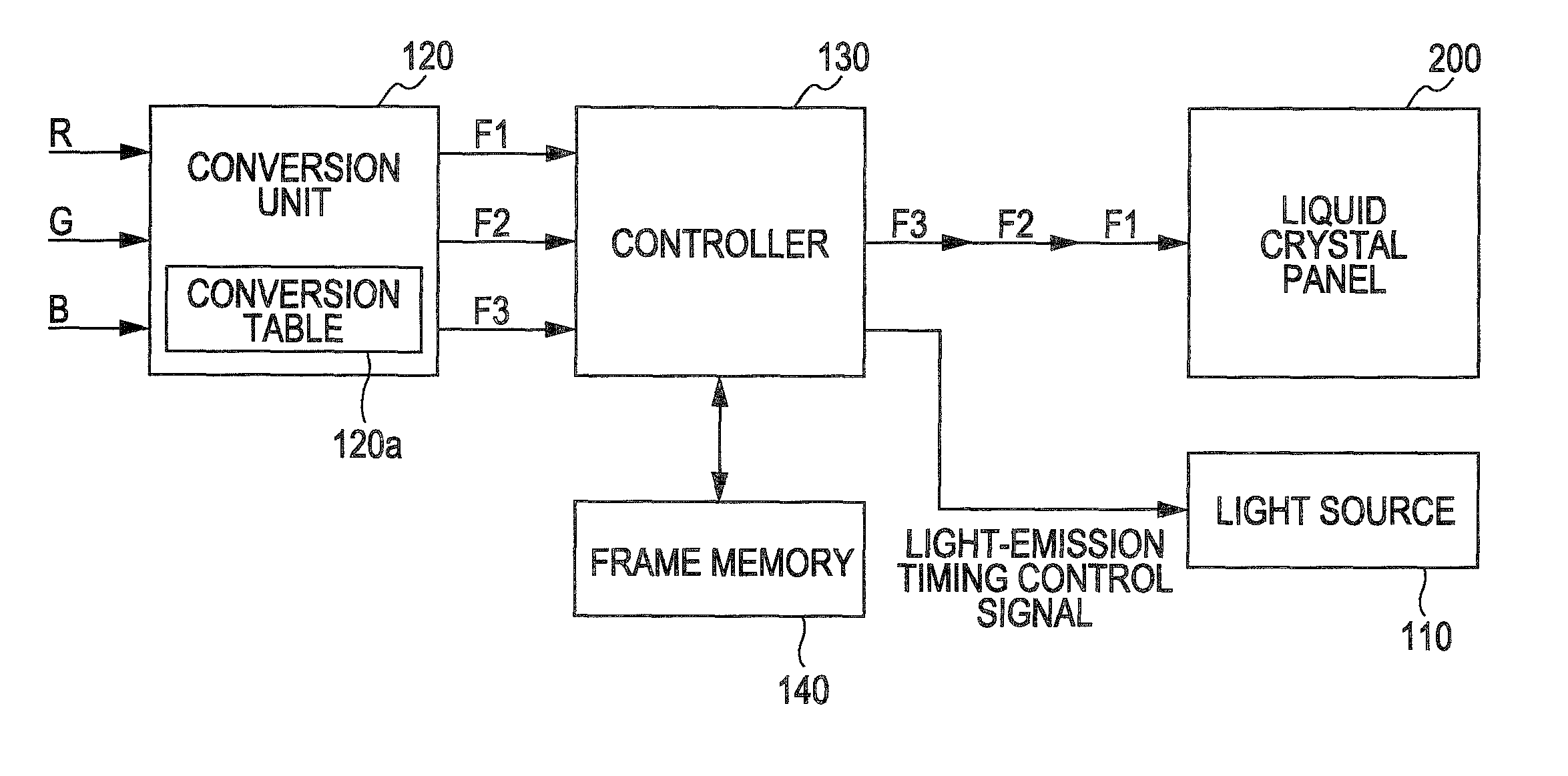
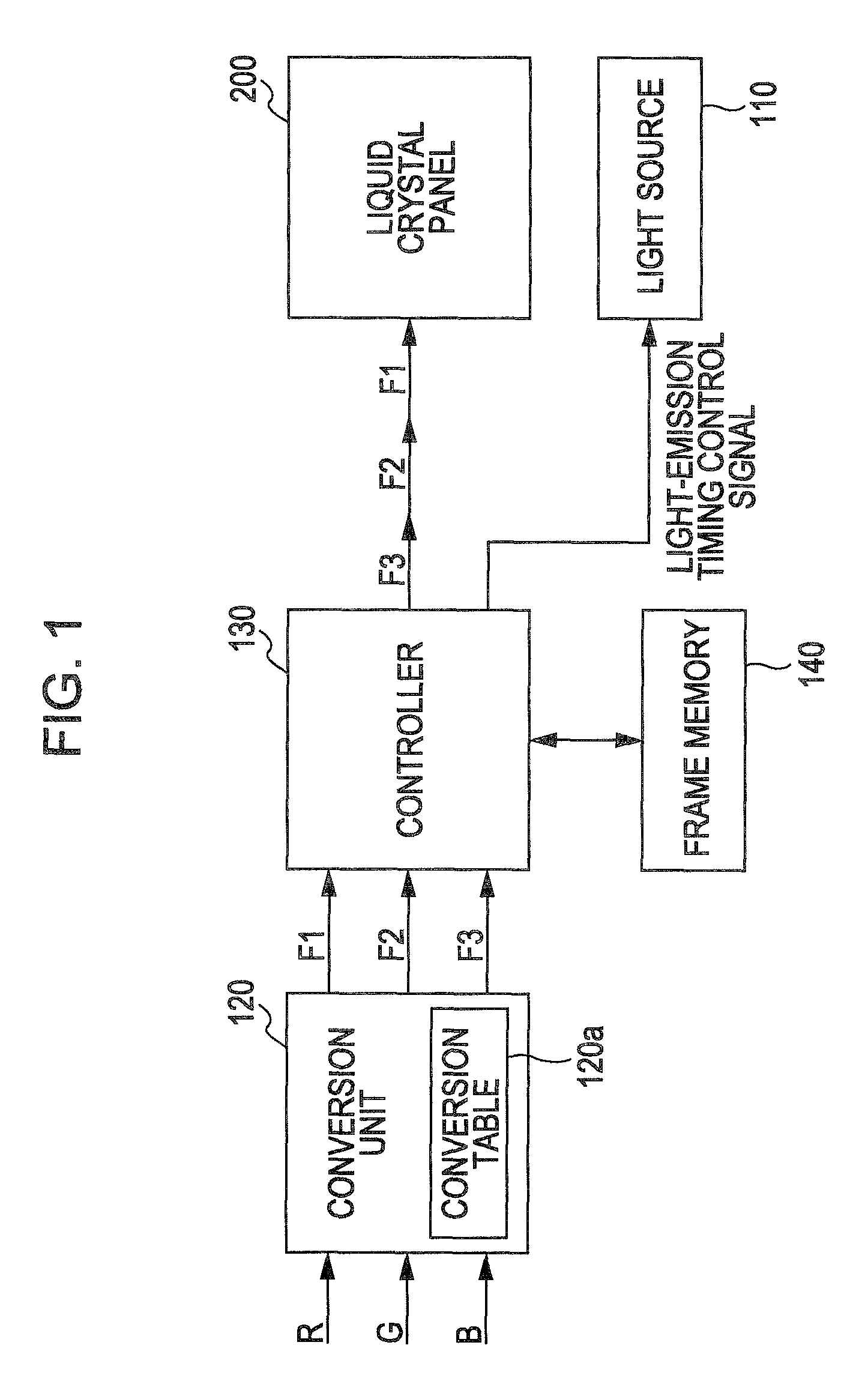
[0064]In the following description, a method / circuit for driving a display device according to an exemplary embodiment of the invention is explained while referring to FIGS. 1-8. It should be noted that the phrase “a circuit for driving a display device” that appears in the following description of this specification as well as in the recitation of appended claims encompasses the meaning of, in addition to its literal meaning, “a driving circuit of a display device” without any limitation thereto. In the following description, a method for driving a display device according to an exemplary embodiment of the invention may be simply referred to as “driving method”. In like manner, a circuit for driving a display device according to an exemplary embodiment of the invention may be simply referred to as “driving circuit”. In the following...


PUM


Abstract

A display device includes a data converting section that converts display data that is to be supplied to pixel units. The data converting section converting on the basis of a predetermined conversion rule for each of a plurality of fields. The plurality of fields corresponds to respective light emission time periods of the plurality of light beams and following one after another in a successive manner on a time axis. The predetermined conversion rule converts data for a preceding field of one color to achieve a value in a successive field of a different color, such that the value approaches a desired value for at least one of brightness and color obtained when an image is displayed in the display area during the successive field.

Description

BACKGROUND[0001]1. Technical Field[0002]The present invention relates to a method for driving various kinds of display devices and a circuit for driving various kinds of display devices. In addition, the present invention relates to an electro-optical device that uses such a driving method or is provided with such a driving circuit and further relates to an electronic apparatus that is provided with such an electro-optical device. An example of a variety of display devices to which the invention is directed is a liquid crystal display device, though not limited thereto. A non-limiting example of a variety of electronic apparatuses to which the invention is directed is a liquid crystal projector.[0003]2. Related Art[0004]In the technical field to which the present invention pertains, a field-sequential driving scheme has been proposed so far as one known method for driving various kinds of display devices such as a liquid crystal display device or the like. In a typical field-sequent...

Claims


Application Information

Patent Timeline
Patent Type & Authority Patents(United States)
IPC IPC(8): G09G3/36
CPCG09G3/3648G09G3/2003G09G2310/0235G09G2320/0242G09G2340/06G09G2340/16G09G3/36G02F1/133G09G3/20
Inventor IISAKA, HIDEHITOHOSAKA, HIROYUKI
Owner SEIKO EPSON CORP
Why Eureka
Try Eureka