This helps you quickly interpret patents by identifying the three key elements:
Problems solved by technology
Method used
Benefits of technology
Benefits of technology
The patent text discusses the use of nanoparticles, such as quantum dots, in solid state lighting. These nanoparticles have the ability to emit light visible to the eye, making them useful in creating high-quality white light with high efficiency. The use of quantum dots as a phosphor in LED applications is particularly promising due to their narrow emission band and high quantum efficiency. For backlight applications, quantum dots are expected to be an important phosphor for improving efficiency. Overall, nanoparticles such as quantum dots are expected to play an important role in advancing the field of LED applications in the near future.
Problems solved by technology
A major problem of QDs towards application is their sensitivity towards oxygen and water.
For example, the non-spherical shape and large size distribution which is obtained upon micro milling will hamper proper mixing of micro particles into a second host, and hinder hermetic encapsulation by a secondary coating.
A too large mismatch between thermal expansions may cause e.g. cracks.
It was found that when using organic micro beads, which are known from the prior art, such micro beads, even when these are substantially spherical, can hardly be coated with an inorganic coating, which is a preferred coating, without substantial mismatch in thermal expansion.
An irregular shape such as obtained by micro milling increases the chance of crack-formation even further in case of a large CTE mismatch.
Method used
Image
Click on the blue label to locate the original text in one second.
Reading with bidirectional positioning of images and text.
Examples
example 1
Preparation of Impregnated Particles
[0191]Trisoperl particles were impregnated according as follows: 1 gram of 5% wt dispersion of Crystalplex QDs in heptanes was added to IBMA / HDDA (5 g). This results in a 1% wt dispersion QDs in IBMA / HDDA, to which 1 gram of PSPs were added, and 0.5% wt photoinitiator (irgacure 184). The powder-acrylate mixture was put on a Buchner funnel, and filtrated for a few minutes in the glovebox. After filtration the powder was cured for 4 minutes with UV light in the glovebox. This results in a sticky powder, which was converted into a loose powder of individual PSPs by dispersing it in toluene and giving it a 15 minute US treatment in a close vial, hence no contact with ambient air. Next, the toluene was removed in the glovebox, by decanting, followed by evacuation of a few hours to remove all toluene. FTIR measurements show that the acrylic has a 95% conversion rate, which means a nearly complete curing of the acrylate. A subset of these particles was m...
[0192]50 mg of the impregnated PSP (batch 1) was spread out over a siliconwafer (outside the glovebox), and inserted into the Emerald chamber (for plasma enhanced ALD) of an ASM dual chamber ALD system. A 50 nm alumina layer was applied using the plasma-enhanced ALD process at 100 C, using TMA (trimethylaluminium) and O2 as reactive gasses. After deposition, the powder was harvested and mixed into Ebecryl 150 (with 1% wt irgacure 184) to make cured films of the ALD-coated PSP's in a secondary matrix. As described above in example 1, reference samples of the same impregnated PSP's without ALD were also made, in addition to films of plain QDs in IBMA / HDDA (no impregnation). In all cases, the samples consisted of a 100 um acrylic layer, in between two glass plates. The QE of the ALD-coated PSP's using plasma enhanced ALD (called sample ALD-a from here on) had a QE of 50%, which is the same as before ALD coating (batch 1, 52%). The ALD coating thus...
example 3
Thermal ALD@150 C on Impregnated PSP
[0200]30 mg of the impregnated PSP (batch 1) was spread out over a siliconwafer (outside the glovebox), and inserted into the Pulsar chamber (for thermal ALD) of an ASM dual chamber ALD system. A 50 nm alumina layer was applied using the thermal ALD process at 150 C, using TMA (trimethylaluminium) and O3 as reactive gasses. After deposition, the powder was harvested and mixed into Ebecryl 150 (with 1% wt irgacure 184) to make cured films of the ALD-coated PSP's in a secondary matrix. The QE of the ALD-coated PSP's using thermal ALD at 150° C. (called sample ALD-b from here on) had a QE of 31%, which is a drop of 20% compared to before ALD coating (batch 1, QE of 52%).
[0201]A small part of the thermal ALD coated particles from ALD-b was used to make cross-sections and investigate in SEM. FIG. 7a shows a SEM image of PSP's with ALD-b coating. In the prepared Schliffs (cross-sections) some of the particles were not fully embedded in the epoxy carrie...
PUM
Property
Measurement
Unit
Length
aaaaa
aaaaa
Length
aaaaa
aaaaa
Light
aaaaa
aaaaa
Abstract
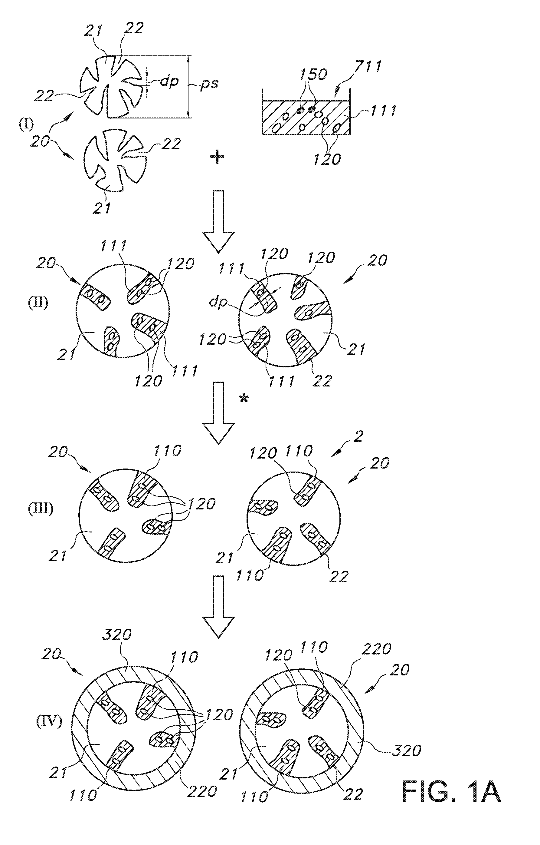
The invention provides a process for the production of a (particulate) luminescent material comprising particles, especially substantially spherical particles, having a porous inorganic material core with pores, especially macro pores, which are at least partly filled with a polymeric material with luminescent quantum dots embedded therein, wherein the process comprises (i) impregnating the particles of a particulate porous inorganic material with pores with a first liquid (“ink”) comprising the luminescent quantum dots and a curable or polymerizable precursor of the polymeric material, to provide pores that are at least partly filled with said luminescent quantum dots and curable or polymerizable precursor; and (ii) curing or polymerizing the curable or polymerizable precursor within pores of the porous material, as well as a product obtainable thereby.
Description
FIELD OF THE INVENTION[0001]The invention relates to a (particulate) luminescent material, as well as to a production process for such (particulate) luminescent material. The invention further relates to a wavelength converter and lighting device comprising such (particulate) luminescent material.BACKGROUND OF THE INVENTION[0002]Quantum dot (QD) based lighting is known in the art. WO2012021643, for instance, describes systems and methods that relate to quantum dot structures for lighting applications. In particular, quantum dots and quantum dot containing inks (comprising mixtures of different wavelength quantum dots) are synthesized for desired optical properties and integrated with an LED source to create a trichromatic white light source. The LED source may be integrated with the quantum dots in a variety of ways, including through the use of a small capillary filled with quantum dot containing ink or a quantum dot containing film placed appropriately within the optical system. T...
Claims
Application Information
Patent Timeline
Application Date:The date an application was filed.
Publication Date:The date a patent or application was officially published.
First Publication Date:The earliest publication date of a patent with the same application number.
Issue Date:Publication date of the patent grant document.
PCT Entry Date:The Entry date of PCT National Phase.
Estimated Expiry Date:The statutory expiry date of a patent right according to the Patent Law, and it is the longest term of protection that the patent right can achieve without the termination of the patent right due to other reasons(Term extension factor has been taken into account ).
Invalid Date:Actual expiry date is based on effective date or publication date of legal transaction data of invalid patent.

