
Bedpan system

a bedpan and system technology, applied in the field of bedpan systems, can solve the problems of personal discomfort, multi-level metal structure that may be difficult to move past the patient's legs, and the patient into a position in which most find defecation nearly impossible, and achieve the effect of replacing anywhere and removing patients

Inactive Publication Date: 2012-07-24
STEFANO SANDRA +1
View PDF14 Cites 4 Cited by
  • Summary
  • Abstract
  • Description
  • Claims
  • Application Information

AI Technical Summary

Benefits of technology

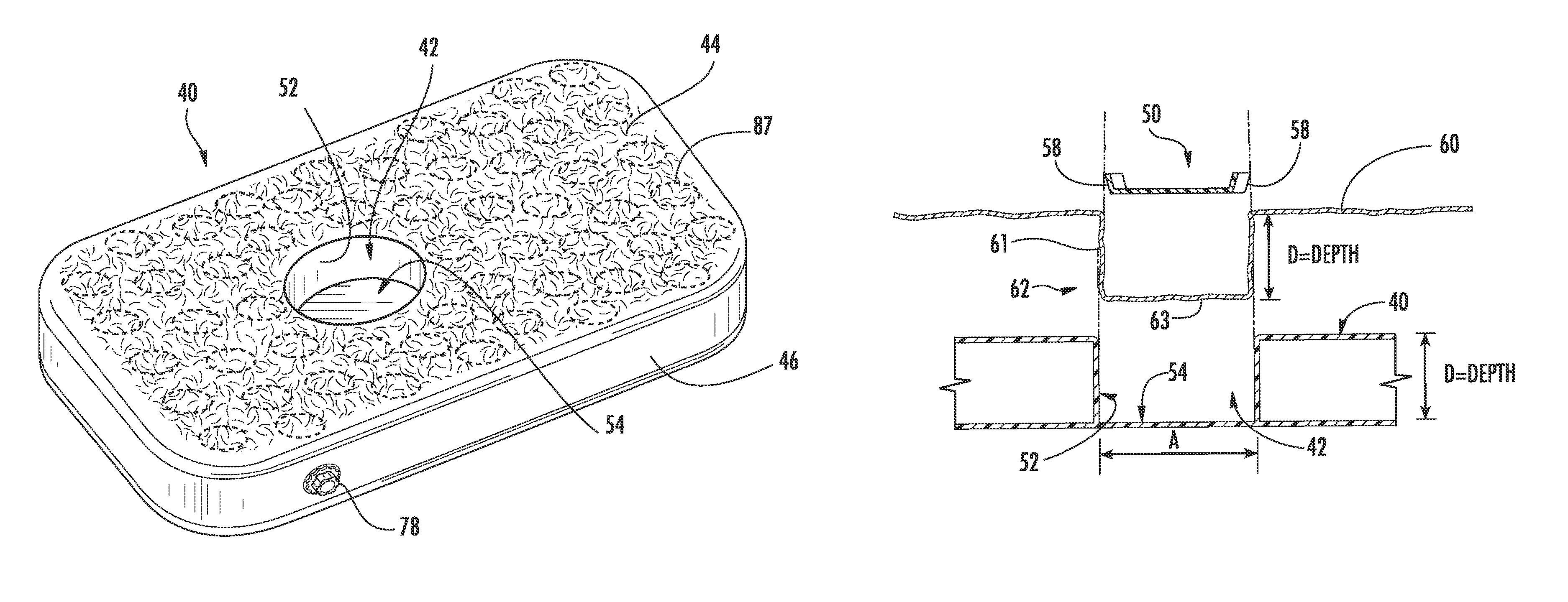
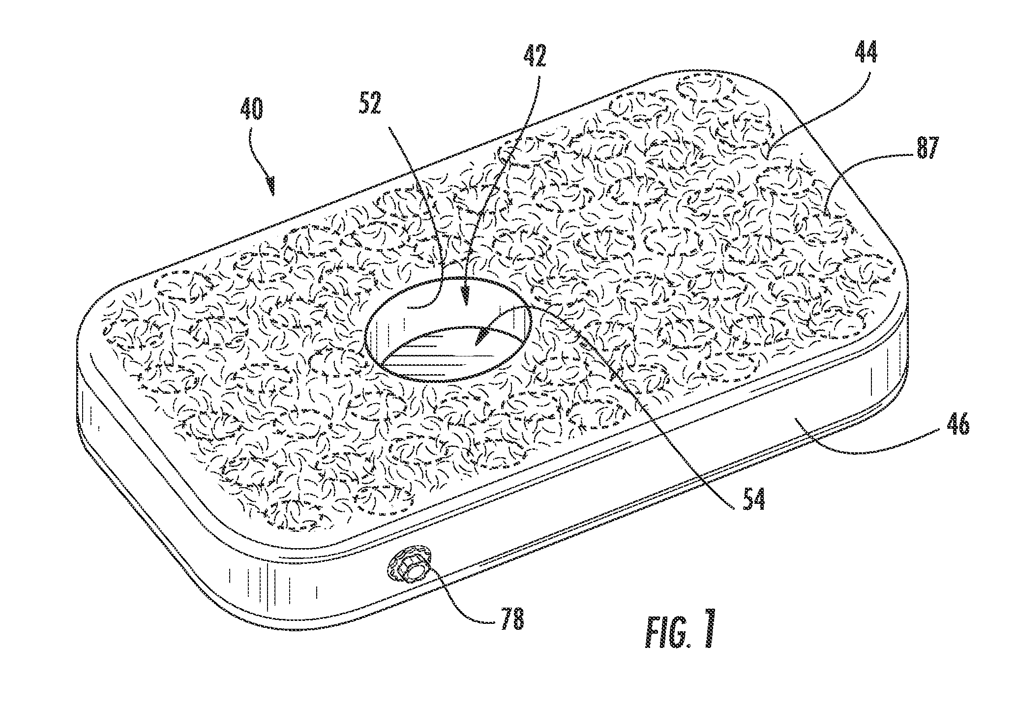
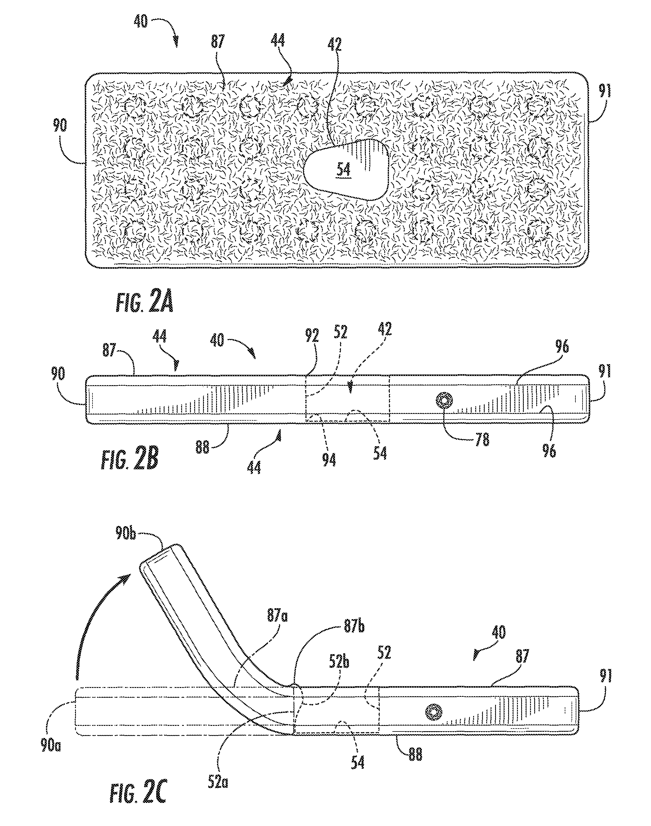
[0020]A full size underlayment (mattress) to be placed onto any hospital bed and / or commercial bed as the only underlayment, or on top of a regular bed mattress. This underlayment can also be made to fit any hospital gurney for post operating rooms, emergency rooms or recovery rooms. The underlayment can be made with a smooth flat surface, but preferably has a cushioning tufted surface for safety and comfort. This underlayment is portable and can be removed and replaced anywhere. The underlayment is an inflated mattress customized with a cavity to accommodate the insertion of a bedpan or bedpan bag or other human waste receptacle. This enables patients to use the waste receptacle while in a supine or seated position on the underlayment.
[0021]The underlayment's entire top and bottom surface is made with a flocked surface to prevent perspiration and sliding. A full outer side wall surrounds the entire underlayment connecting the top and bottom surface for stability. The bottom surface is one piece and solidly closed-in under the cavity.
[0026]The cushion is made of foam material with a soft top surface which is attached to a flexible plastic base for easy insertion and removal, while supplying stability as it rests on the top of receptacle's surface. If so desired, a full foam cushion can also be used to fill in entire cavity without the receptacle.

Problems solved by technology

The discomfort is especially critical for patients whose condition requires them to remain nearly horizontal, not allowing the patient to be raised to approach a sitting position.
In such situations, the elevation of the hips caused by a bedpan inserted between the patient and a flat supporting surface puts the patient into a position in which most find defecation nearly impossible.
Little need be said of the personal discomfort that arises from sustained periods during which defecation is denied, not to mention the physiologic difficulties that may result, such as diverticulitis or impaction.
Apparent limitations: Hayes' support ring portion (54) that rests on the top surface of the mattress could be irritating if left in place, and the support ring (53-55 as seen in Hayes' FIG. 17) appears to be a formed wire, multilevel metal structure that may be difficult to move past the patient's legs if they can't be lifted.
Hayes' full size cavity plug would be very difficult to remove when a patient is present.
Apparent limitations include a complex mattress design including difficult to clean recesses, a bedpan that may need to be removed in order to clean it if needed, and a cavity that isn't fully enclosed—therefore being difficult to de-contaminate in the event of spills.
The plug appears to be rather bulky and therefore difficult to insert / remove under a patient.
Furthermore, by extending the first fitted sheet within the cut-out portion the first fitted sheet is thereby secured about the perimeter of the cut-out portion, so that the mattress will not readily be uncovered.
Although Ruff's first fitted sheet may be held wrinkle free, it appears that the second fitted sheet is not well enough secured by its elastic bands, and furthermore does not provide a convenient way to grasp and pull out the insert when a patient is lying thereupon.

Method used


Image

  • Bedpan system
  • Bedpan system
  • Bedpan system

Examples


Embodiment Construction

[0055]The present disclosure concerns one or more inventions providing a bedpan system specially adapted for use by bedridden patients, especially those patients who cannot be moved from a supine position. In general, a bedpan system 100 according to the present invention comprises the following “component” groupings of elements, sub-elements, features, aspects, and characteristics, both separately and in various combinations:[0056]a. An underlayment 40 comprising: a mattress, preferably an inflatable mattress constructed substantially of flexible plastic sheet material, and having one or more flocked surfaces 44.[0057]b. A mattress cavity 42 open at its top, having a substantially vertical inner side-wall 52, a closed bottom (base) 54, and smooth junctions at seams 92, 94 of the plastic sheet material. Preferably the cavity shape A, in top view, is narrowed toward a head 90 of the underlayment 40.[0058]c. A bed sheet 60 having a pocket 62 that is positioned and sized to closely fit...


PUM


Abstract

A bedpan system including an underlayment for supporting a supine human patient above a substantially horizontal supporting surface, wherein the underlayment has: a substantially horizontal top surface upon which the patient rests, a substantially parallel, spaced apart bottom surface for lying upon the supporting surface, and a bedpan cavity having an open top in registry with buttocks of the patient; the bedpan system comprising: an underlayment that is an inflatable mattress constructed substantially of flexible plastic sheet material comprising: a top sheet providing the top surface, a bottom sheet providing the bottom surface, side wall sheets attached between the top sheet and the bottom sheet providing substantially vertical side walls around the perimeter of the underlayment when it is inflated, and cavity sidewall sheets attached between the top sheet and the bottom sheet providing substantially vertical sidewalls in the cavity; a cavity base that is joined to the cavity sidewalls as a closed bottom for the cavity, thereby effectively making the bottom surface of the underlayment a single, unitary, or continuous sheet including under the cavity; a smooth junction where the cavity sidewalls join with the top surface; and a smooth junction where the cavity sidewalls join with the cavity base.

Description

CROSS-REFERENCE TO RELATED APPLICATIONS[0001]This application claims the benefit of U.S. Provisional Patent Application No. 61 / 117,977, filed Nov. 26, 2008 by Stefano et al.[0002]The bedpan system of the present invention is particularly related to a patient underlayment device (mattress) similar to that of previous U.S. Pat. No. 4,949,409, PNEUMATIC PATIENT LIFT TO AID BEDPAN USE, to the method of previous U.S. Pat. No. 5,081,721, METHOD OF USING INFLATABLE PATIENT SUPPORT WITH A BEDPAN, and to the DISPOSABLE BEDPAN SYSTEM FOR USE WITH ELEVATED PATIENT SUPPORT of U.S. Pat. No. 6,000,078; all issued to the present inventor, Sandra Stefano. Therefore, the disclosures of U.S. Pat. Nos. 4,949,409 and 5,081,721 and 6,000,078 are incorporated in their entirety herein by reference.TECHNICAL FIELD OF THE INVENTION[0003]The present invention relates to a bedpan system comprising a combination of an elevated patient support and a flexible bedpan for deployment in a cavity of the patient supp...

Claims


Application Information

Patent Timeline
Patent Type & Authority Patents(United States)
IPC IPC(8): A47C17/00
CPCA61G7/02A61G9/003
Inventor STEFANO, SANDRAMARTIN, ANTHONY G.
Owner STEFANO SANDRA
Learn More