Light steel structural members

a technology of structural members and light steel, applied in the field of structural members, can solve problems such as unfavorable bumps

Active Publication Date: 2012-07-24
PARADIGM FOCUS PROD DEV
View PDF25 Cites 138 Cited by
  • Summary
  • Abstract
  • Description
  • Claims
  • Application Information

AI Technical Summary

Problems solved by technology

For lateral building stability the C-Shape bracing connections can be three material layers thick at the top and bottom of the wall structure, which causes unsightly bumps to prevail in the finished gypsum and sheathing applications.

Method used


Image

  • Light steel structural members
  • Light steel structural members
  • Light steel structural members

Examples


Embodiment Construction

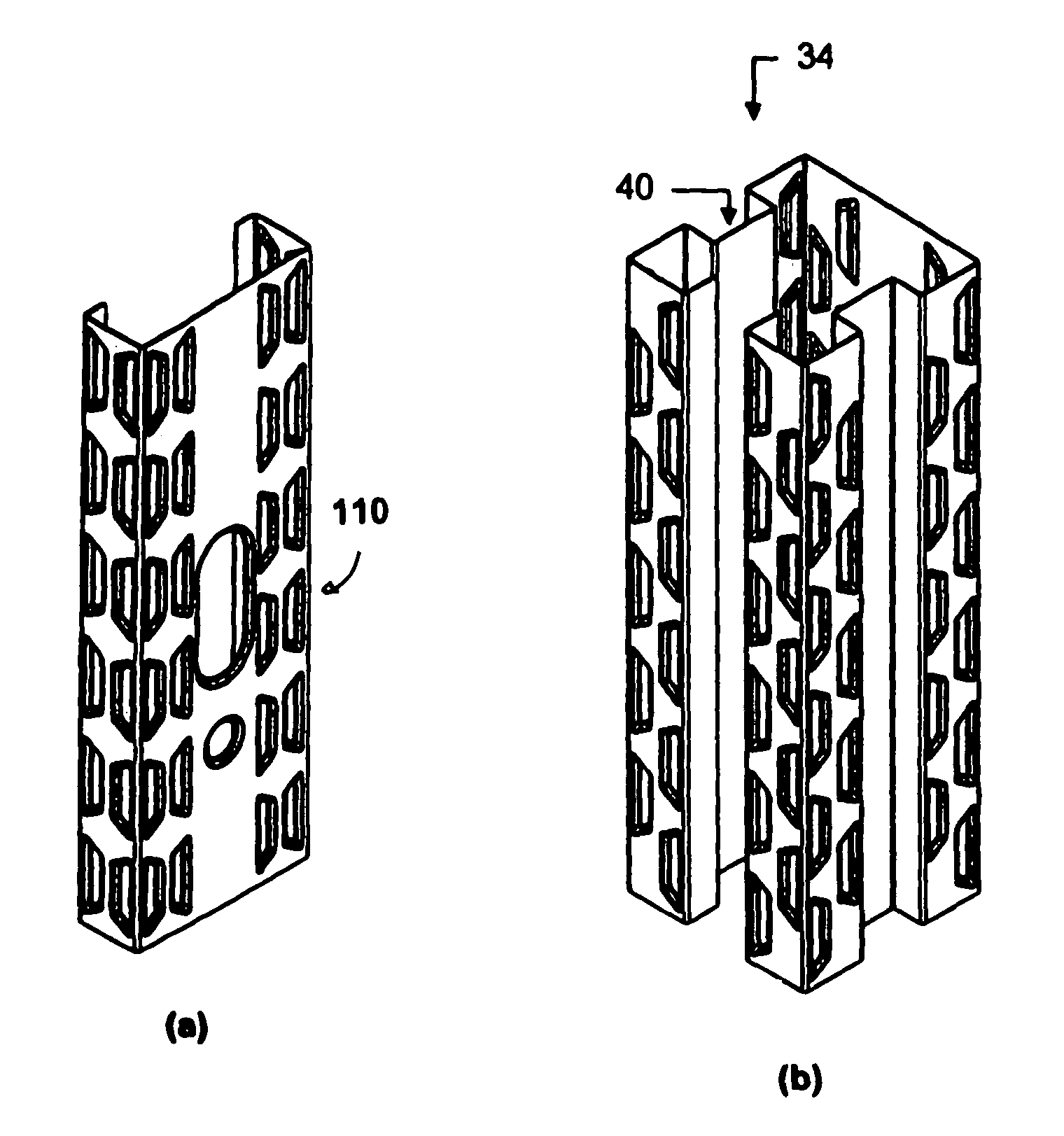
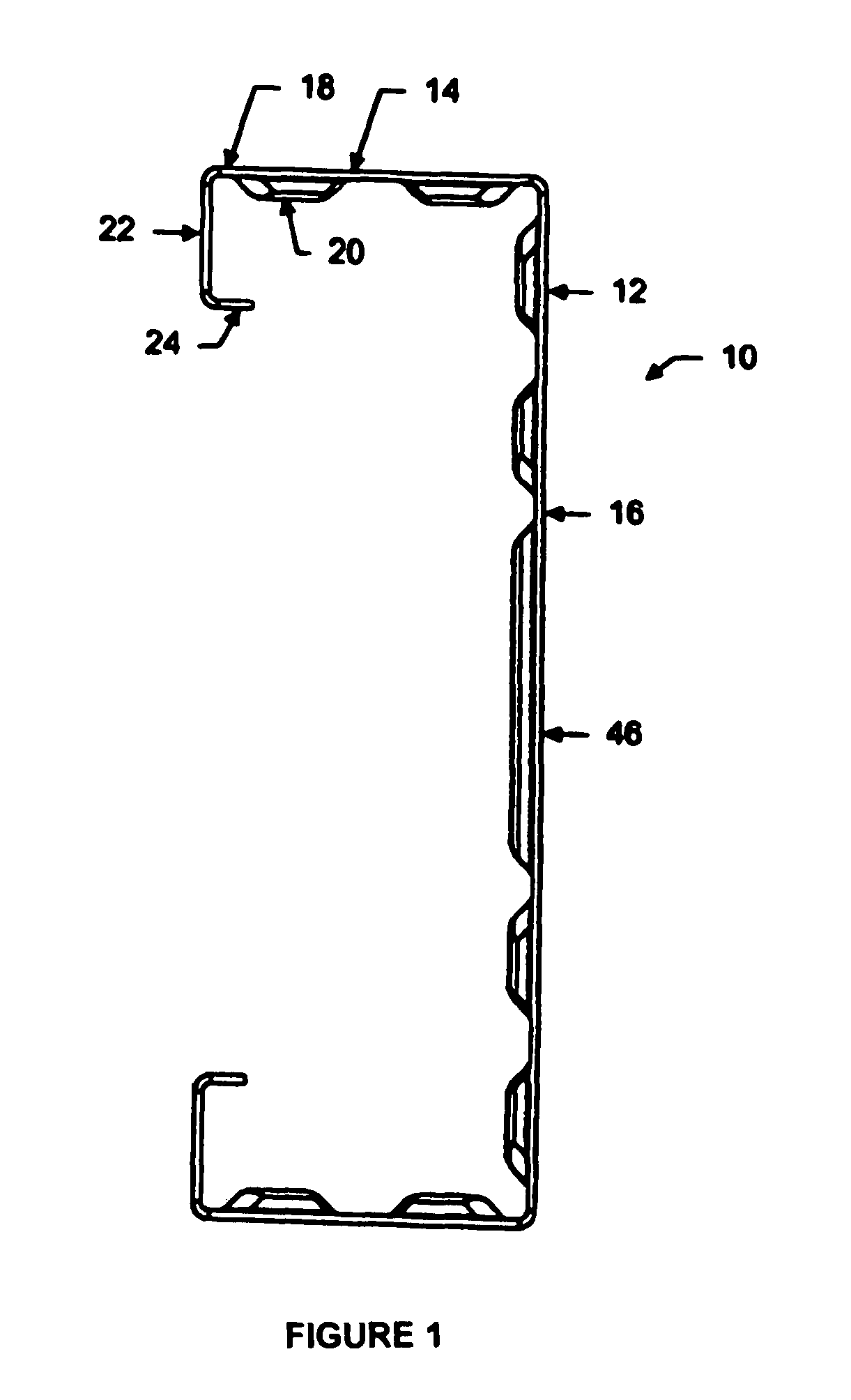
[0070]Referring to figures, FIG. 1 shows the light steel structural member of the present invention generally at 10. The light steel structural member 10 includes a web portion 12 and a pair of flange portions 14. The web portion has a web face 16. The pair of flange portions 14 each extend generally orthogonally from each end of the web portion 12. The flange portions 14 are generally parallel to each other. Each flange portion 14 has a flange face 18. At least one of the web face 16 and the flange face 18 has a plurality of embosses 20 formed therein. Preferably member 10 also includes a pair of flange lips 22 extending inwardly from flange 14. The flange lips 22 extend generally orthogonally from each flange generally parallel to the web 12. A flange lip stiffener 24 which extends inwardly from flange lips 22 may also be used to further improve the structural characteristics of the member 10.

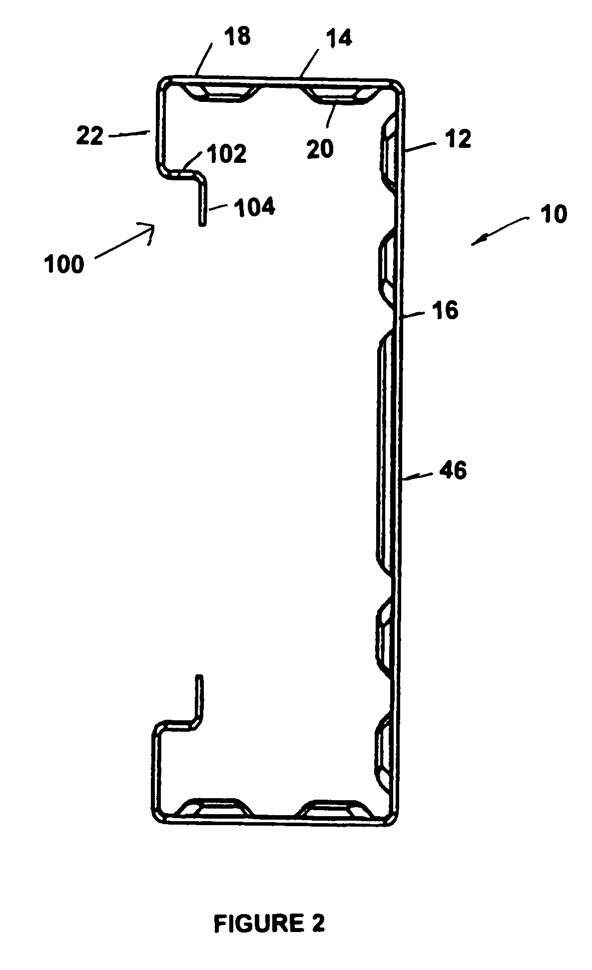
[0071]FIGS. 2 and 3 show another variation in regard to the flange portion 14 including a...


PUM

PropertyMeasurementUnit
thicknessaaaaaaaaaa
shapeaaaaaaaaaa
widthaaaaaaaaaa

Abstract

A light steel structural member includes a web portion and a pair of flanges. The web portion has a web face. The pair of flange portions each extend generally orthogonally from each end of the web portion. The flange portions each having a plane and the planes are generally parallel each other and each flange has a flange face. At least one of the web face and the flange face has a plurality of embosses formed therein. In another embodiment the light steel structural member further includes a pair of restraining ribs. In a further embodiment the light steel structural member further includes a pair of lips and a pair of multi-cranked stiffeners. A method of making the light steel structural members is shown.

Description

CROSS REFERENCE TO RELATED PATENT APPLICATION[0001]This patent application relates to U.S. Provisional Patent Application Ser. No. 60 / 801,055 filed on May 18, 2006 entitled Light Steel Structural Studs which is incorporated herein by reference in its entirety.FIELD OF THE INVENTION[0002]This invention relates to structural members and in particular structural members made from light steel and structural members made from light steel and concrete.BACKGROUND OF THE INVENTION[0003]For the construction of buildings Light Steel Framed (LSF) structures have been gaining acceptance in various segments of the construction market. The C-Shape section has gained its greatest acceptance in wall applications, primarily as exterior curtain and wind wall applications and for interior partition walls. For high structural gravity loads and spanning wall openings C-Shapes are often thicker to suit increased loads. On multi-floor LSF buildings C-Shapes are bunched and connected together to suit high ...

Claims


Application Information

Patent Timeline
Patent Type & Authority Patents(United States)
IPC IPC(8): E04C3/00
CPCE04C3/07E04C2/384E04C3/32E04C5/03E04C3/09Y10T29/49632E04C2003/0413E04C2003/0421E04C2003/043E04C2003/0465E04C2003/0473Y10T428/12354Y10T29/49616Y10T29/49627Y10T29/49623Y10T29/5136E04B2/763E04B2/765E04B2/767E04B2/7854E04B2/789E04B2001/2496
Inventor STRICKLAND, MICHAEL R.FOX, DOUGLAS M.STRICKLAND, RICHARD WILSON
Owner PARADIGM FOCUS PROD DEV
Why Eureka
Try Eureka