Image display apparatus featuring improved contrast

a technology of image display and contrast, which is applied in the field of image display apparatus, can solve the problems of image correction becoming demerit rather than merit, difficulty for the related art to reduce the deterioration of fine gradation, and the fine gradation expression of the white side image may be deteriorated, so as to improve the sensible contrast feeling, increase the luminance level of video signal, and improve the effect of luminan

Inactive Publication Date: 2012-07-24
SONY CORP
View PDF14 Cites 1 Cited by
  • Summary
  • Abstract
  • Description
  • Claims
  • Application Information

AI Technical Summary

Benefits of technology

[0009]Thus, when the light quantity from the light source is changed with the video signal, it may have been difficult for the related art to reduce the deterioration of fine gradation expression while improving sensible contrast feeling.
[0010]It may be desirable to provide an image display apparatus capable of reducing the deterioration of fine gradation expression while improving sensible contrast feeling, when the light quantity from the light source is changed with the video signal.
[0012]In the image display apparatus of the embodiment of the preset invention, the light from the light source may be modulated by the spatial light modulation element based on the video signal, enabling the image display to be performed based on the video signal. Here, the light quantity adjustment of the light from the light source may be performed based on the luminance information represented by the video signal, and the correction of the video signal may be performed to increase the luminance level of the video signal as the light quantity is adjusted to decrease by the light quantity adjustment means. Then, the corrected video signal may be supplied to the spatial light modulation element. Consequently, the black side (the dark side) image luminance may be lowered to improve sensible contrast feeling. Further, when the above-mentioned final display luminance level is higher than a predetermined luminance level, of a light quantity adjustment target and a luminance level correction target, at least the luminance level correction target may be re-adjusted to a value in an opposite direction from correction direction by the image correction means. This may enable the excessive light quantity adjustment and image correction to be reduced in the white side (the bright side) image.
[0013]The re-adjustment means may preferably re-adjust, in the case that the final display luminance level is higher than the predetermined luminance level, the light quantity adjustment target into a non-adjusted value, and re-adjust the luminance level correction target into a non-corrected value. In this case, the light quantity of the light from the light source and the luminance level of the video signal may be re-adjusted to the pre-adjustment value and the pre-correction value, respectively, thereby completely eliminating the excessive light quantity adjustment and image correction. Therefore, the deterioration of fine gradation expression may be avoided, thereby maintaining the state prior to the light quantity adjustment and the image correction.
[0014]The light quantity adjustment means may asymptotically adjust, frame by frame, the light quantity of the light from the light source based on the light quantity adjustment target re-adjusted by the re-adjustment means. In this case, for example, when displaying the image having large luminance variations with time, such as the image having frequent flickering, the discontinuity in light quantity adjustment amount and image correction amount may be reduced to suppress the transient influence.
[0015]According to the image display apparatus of the embodiment of the present invention, the light quantity adjustment of the light from the light source may be performed based on the luminance information represented by the video signal, and the correction of the video signal may be performed to increase the luminance level of the video signal as the light quantity is adjusted to decrease by the light quantity adjustment means. Then, the corrected video signal may be supplied to the spatial light modulation element. Consequently, the black side (the dark side) image luminance may be lowered to improve sensitive contrast feeling. Further, when the above-mentioned final display luminance level is higher than a predetermined luminance level, of a light quantity adjustment target and a luminance level correction target, at least the luminance level correction target may be re-adjusted to a value in an opposite direction from correction direction by the image correction means. This may enable the excessive light quantity adjustment and image correction to be reduced in the white side (the bright side) image. Hence, when the light quantity from the light source is changed with the video signal, the deterioration of fine gradation expression may be reduced while improving sensible contrast feeling.

Problems solved by technology

When this state is held over a long period of time, the improved sensible contrast feeling owing to the light quantity adjustment and the image correction may become demerit rather than merit.
Specifically, for example, if this state appears in the scene of a blue sky with clouds, the fine tone of the clouds may be vanished, that is, the fine gradation expression of the white side image may be deteriorated.
This disadvantage occurs mostly in the cases where the image correction causes a luminance region having an expanded luminance level range and a luminance region having a compressed luminance level range, and the image region accounting for a small proportion of the entire input image is the image region as being significant expression and located on the latter luminance region.
Thus, when the light quantity from the light source is changed with the video signal, it may have been difficult for the related art to reduce the deterioration of fine gradation expression while improving sensible contrast feeling.

Method used


Image

  • Image display apparatus featuring improved contrast
  • Image display apparatus featuring improved contrast
  • Image display apparatus featuring improved contrast

Examples


Embodiment Construction

[0024]An embodiment of the present invention will now be described in detail with reference to the accompanying drawings.

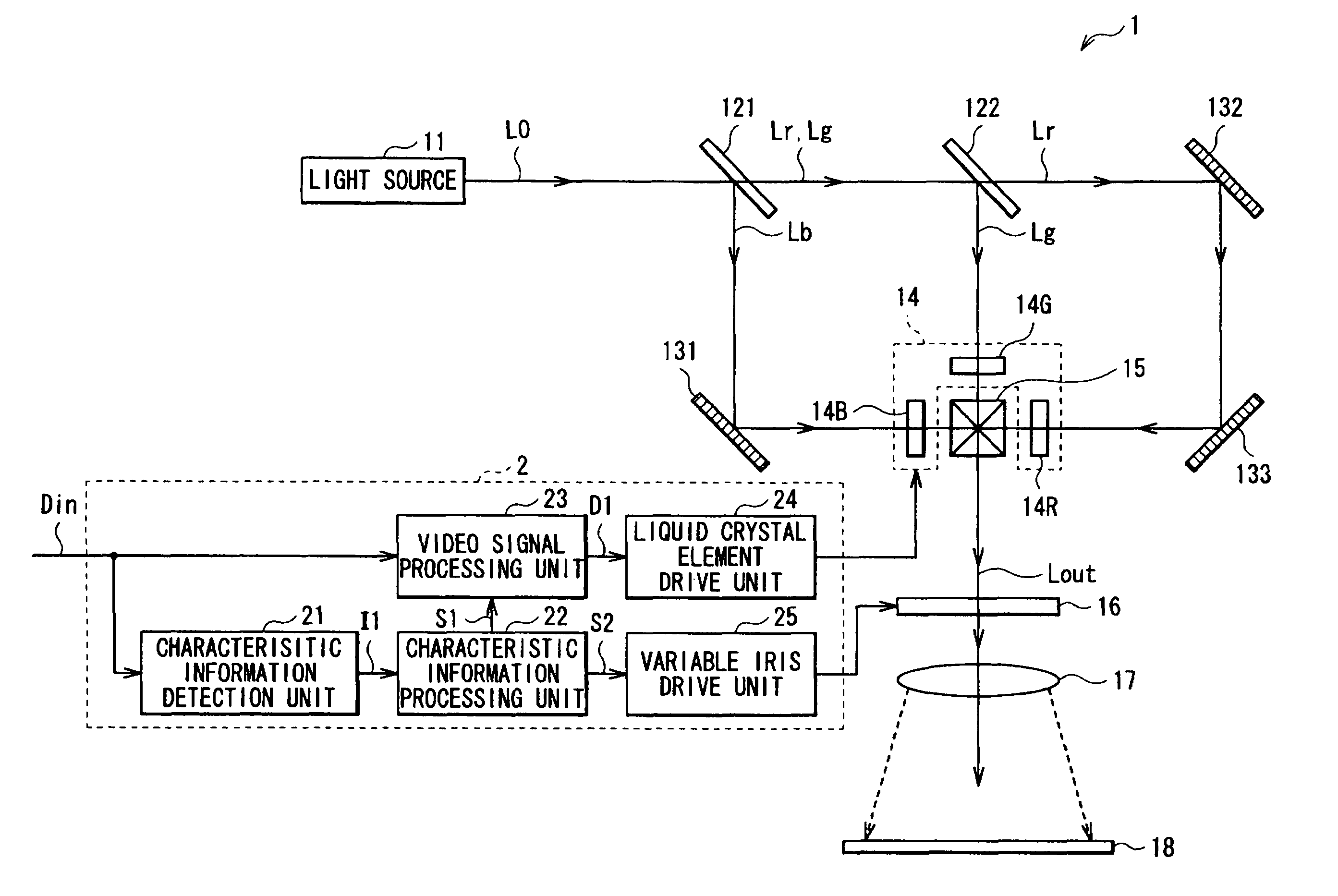
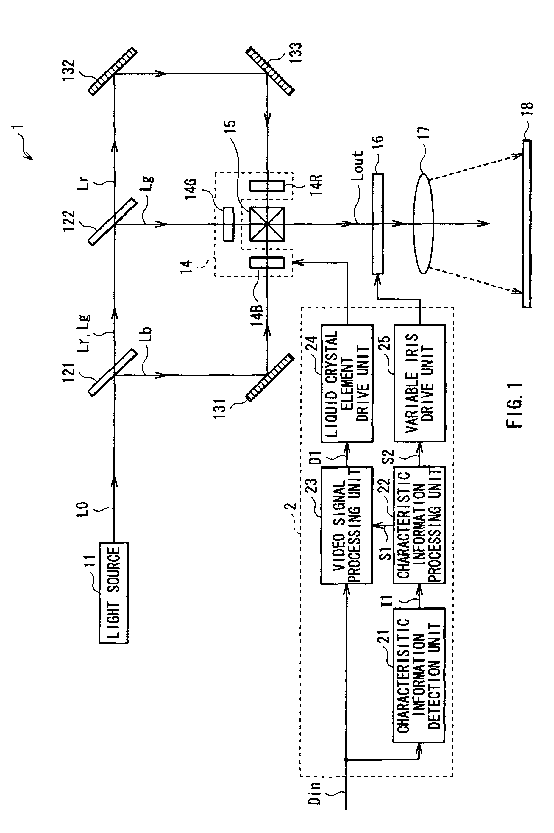
[0025]FIG. 1 shows the overall configuration of an image display apparatus (a liquid crystal projector 1) according to an embodiment of the invention. The liquid crystal projector 1 performs image display based on an input video signal Din supplied from the external, and includes a light source 11, dichroic mirrors 121 and 122, reflection mirrors 131, 132 and 133, a light modulator 14, a dichroic prism 15, a variable iris 16, a projection lens 17, a screen 18, and a controller 2 to control the light modulator 14 and the variable iris 16, based on the input video signal Din.

[0026]The light source 11 emits white light (illumination light) containing the primary colors of light, namely red light Lr, green light Lg and blue light Lb, and is constructed from, for example, a halogen lamp, a metal halide lamp or a xenon lamp.

[0027]The dichroic mirror 121 transmits the re...


PUM


Abstract

An image display apparatus may include a light source, a spatial light modulation element, light quantity adjustment section, image correction section and re-adjustment section. The re-adjustment section may perform re-adjustment such that, of a light quantity adjustment target and a luminance level correction target, at least the luminance level correction target is re-adjusted to a value in an opposite direction from a correction direction by the image correction section, in a case that a final display luminance level, representing a luminance of the light modulated by the spatial modulation element, is higher than a predetermined luminance level, where the luminance level correction target represents a correction target value in the luminance level of the video signal, employed by the image correction section, and the light quantity adjustment target represents a adjustment target value in the light quantity, employed by the light quantity adjustment section.

Description

CROSS-REFERENCE TO RELATED APPLICATIONS[0001]The present application claims priority from Japanese Patent Application No. JP 2007-224515, filed in the Japanese Patent Office on Aug. 30, 2007, the entire content of which is incorporated herein by reference.BACKGROUND OF THE INVENTION[0002]1. Field of the Invention[0003]The present invention relates to an image display apparatus applied to liquid crystal projectors and the like.[0004]2. Description of the Related Art[0005]Projection display apparatuses, such as liquid crystal projectors, have been widely used in which image display is performed by applying spatial modulation to the light passing through a spatial light modulation element, and emitting the light thus modulated, and then collecting and projecting the emitted light in response to the electric signal supplied to the spatial light modulation element. The projection display apparatus of this type generally has a lamp and a focusing mirror as a light source, and an illuminat...

Claims


Application Information

Patent Timeline
Patent Type & Authority Patents(United States)
IPC IPC(8): G09G5/10G09G3/10G09G5/02G03B21/20
CPCG03B21/00G09G3/002G09G3/3406G09G3/3611H04N5/57H04N9/3155H04N21/44008H04N21/4402G09G2320/0238G09G2320/0646G09G2320/0673G09G2360/16G03B21/005G09G3/36G09G3/20G02F1/133G09G5/06
Inventor MIURA, ARUO
Owner SONY CORP
Why Eureka
Try Eureka