Organic electroluminescence display device

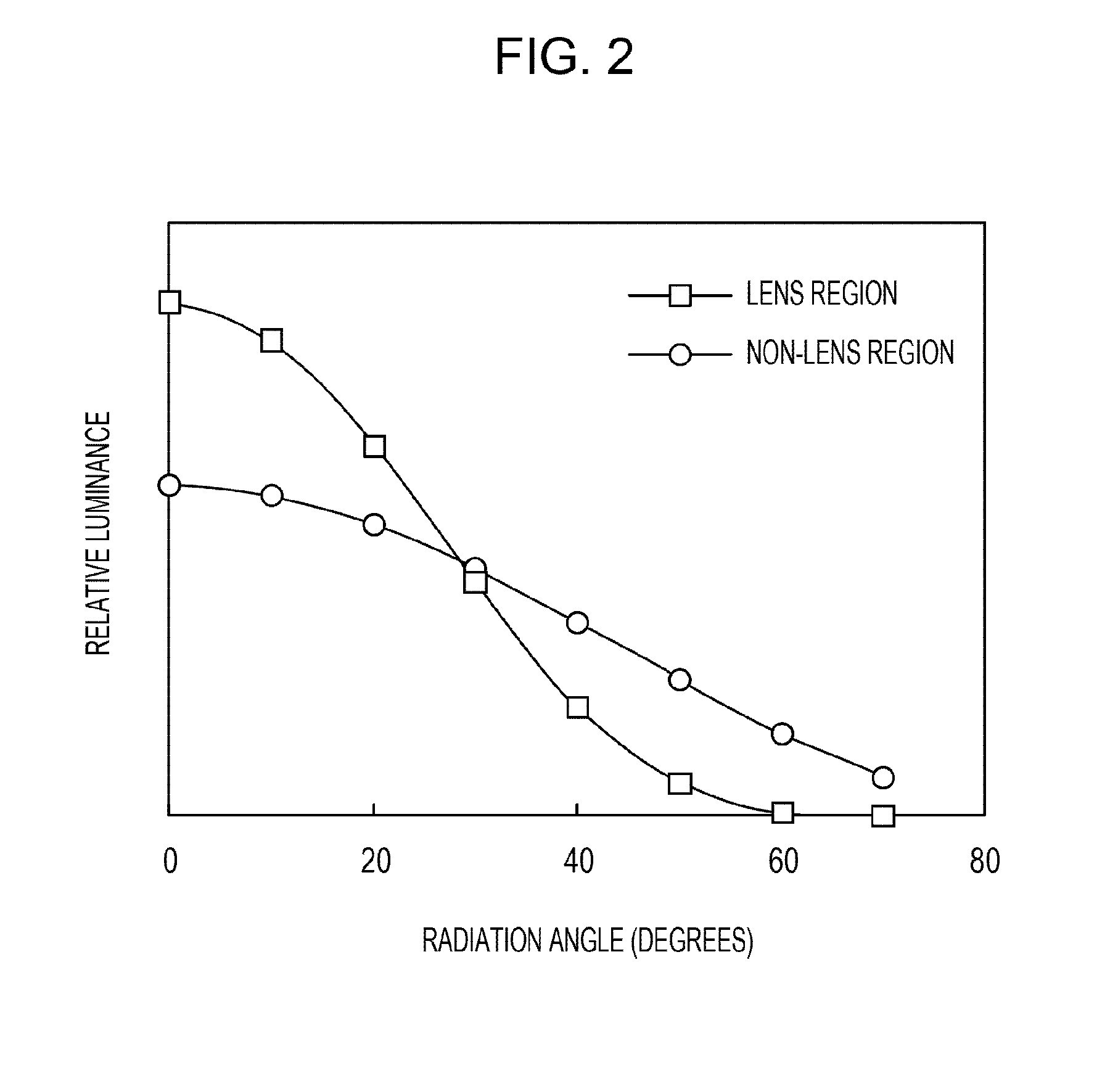
a display device and electroluminescence technology, applied in the direction of discharge tube luminescnet screens, discharge tube/lamp details, electric discharge lamps, etc., can solve the problems of low extraction efficiency of organic light-emitting diodes, low light extraction efficiency, etc., and achieve the effect of wide radiation angle characteristics and improved light utilization efficiency

Inactive Publication Date: 2012-08-14
CANON KK
View PDF3 Cites 0 Cited by
  • Summary
  • Abstract
  • Description
  • Claims
  • Application Information

AI Technical Summary

Benefits of technology

[0006]The present invention provides a display device with wide radiation angle characteristics and improved light utilization efficiency in an organic EL display device.
[0008]According to the present invention, in an organic EL display device provided with a lens, a lens diameter can be increased for enhanced light collection efficiency. It is therefore possible to provide an organic EL display device with wide radiation angle characteristics kept by a lens and with improved light utilization efficiency.

Problems solved by technology

A technical problem for organic EL devices, such as organic light-emitting diodes (OLEDs) is low light extraction efficiency.
In these terms, the extraction efficiency of an organic EL device is low because, since light is emitted at various angles from a light emitting layer in the organic EL device, total reflection components often appear at the interface between a protective layer and an external space and thereby the emitted light is trapped inside the organic EL device.
In the form disclosed in Japanese Patent Laid-Open No. 2004-39500, however, brightness of the display device in oblique directions (peripheral region of the lens) is low and therefore radiation angle characteristics are negatively affected.

Method used


Image

  • Organic electroluminescence display device
  • Organic electroluminescence display device
  • Organic electroluminescence display device

Examples


Embodiment Construction

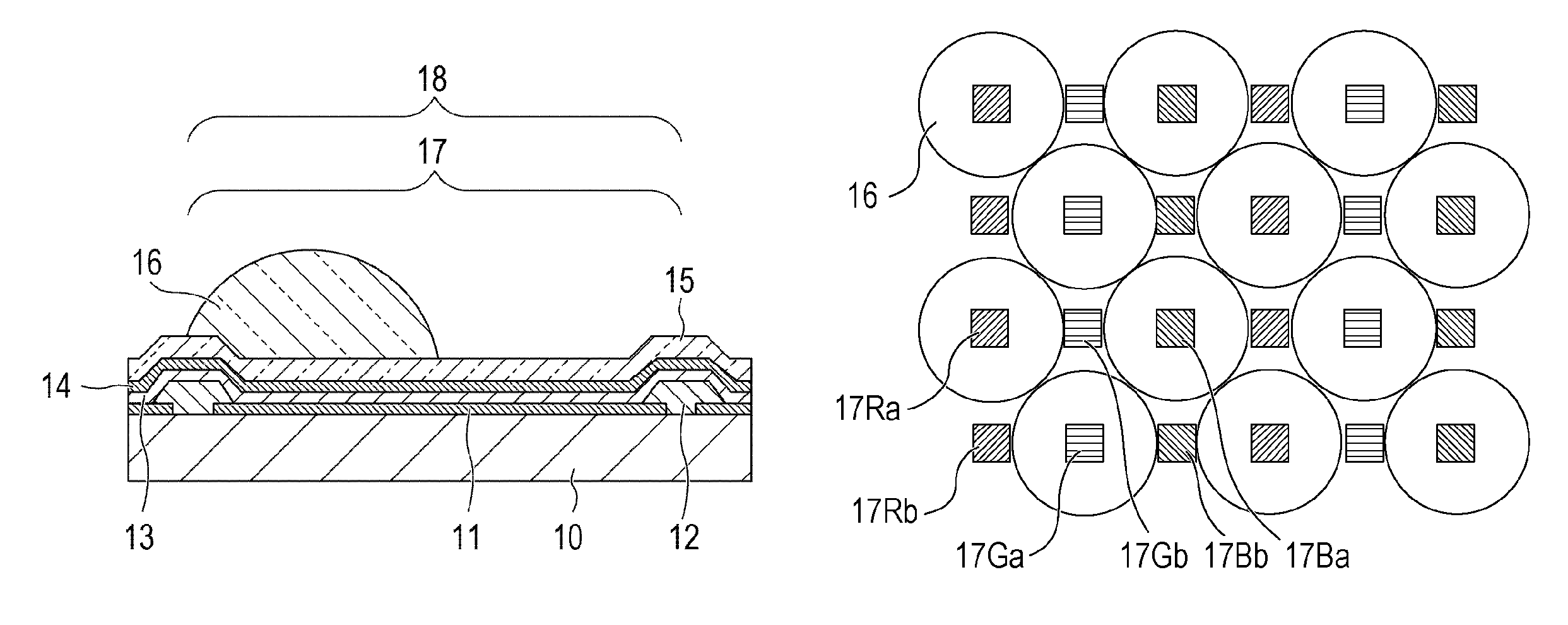
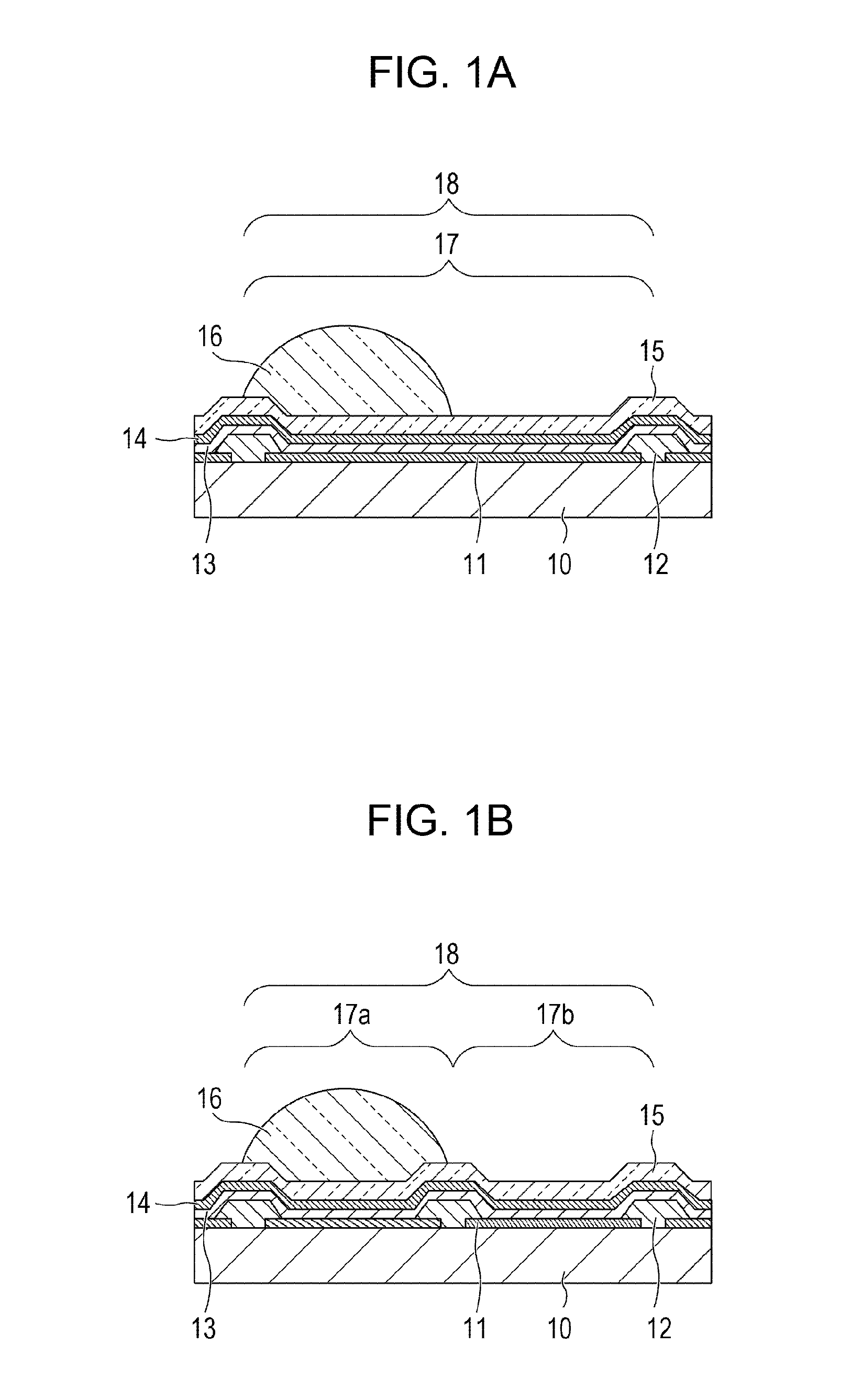
[0018]An organic electroluminescence display device (an organic EL display device) according to the present invention includes a plurality of pixels each of which includes an organic electroluminescence device (an organic EL device) and a lens. Each pixel includes a light emitting region provided with a lens and a light emitting region provided with no lens. The lenses situated in the plurality of pixels are arranged in an alternate (staggered) pattern. Embodiments of the present invention may be implemented at least in the following two configurations in terms of correspondence relationship between the lens and the organic EL device.

[0019]In a first configuration, a single pixel is constituted by a single organic EL device; each organic EL device includes a light emitting region provided with a lens and a light emitting region provided with no lens.

[0020]In a second configuration, a single pixel includes a plurality of organic EL devices which emit the same colored light; one of th...


PUM


Abstract

An organic electroluminescence display device includes a plurality of pixels and an array of lenses arranged thereupon. Each pixel includes a light emitting region provided with a lens and a light emitting region provided without a lens. The light emitting regions of each pixel includes an organic electroluminescence material. The lenses are arranged in a staggered pattern.

Description

BACKGROUND OF THE INVENTION[0001]1. Field of the Invention[0002]The present invention relates to a display device incorporating an organic electroluminescence (EL) device and, more particularly, to a display device incorporating an organic EL device capable of enhancing light utilization efficiency from the top of the display device.[0003]2. Description of the Related Art[0004]A technical problem for organic EL devices, such as organic light-emitting diodes (OLEDs) is low light extraction efficiency. Light extraction efficiency may be generally defined as the fraction of light radiated outside of the OLED out of the out of the total optical power generated in the active layer (light-emitting layer) of the OLED. In these terms, the extraction efficiency of an organic EL device is low because, since light is emitted at various angles from a light emitting layer in the organic EL device, total reflection components often appear at the interface between a protective layer and an externa...

Claims


Application Information

Patent Timeline
Patent Type & Authority Patents(United States)
IPC IPC(8): H01J1/62
CPCH01L51/5275H10K50/858
Inventor MORIYAMA, TAKASHISHIKINA, NORIYUKISATO, NOBUHIKO
Owner CANON KK
Why Eureka
Try Eureka