LED optical assembly for automotive headlamp

a low-beam headlamp and optical assembly technology, applied in vehicle headlamps, transportation and packaging, lighting and heating apparatus, etc., can solve the problems of low light utilization efficiency, difficult to achieve the effect of reducing the volume of the optical assembly, simplifying the structure, and improving the utilization efficiency of ligh

Inactive Publication Date: 2012-12-06
TIANJIN FONCOL SCI & TECH DEV
View PDF6 Cites 15 Cited by
  • Summary
  • Abstract
  • Description
  • Claims
  • Application Information

AI Technical Summary

Benefits of technology

[0015]Advantages of the invention are summarized below. Via the main lens, the LED optical assembly forms a section of straight light area with cut-off lines and without obvious dispersion in the front. Lateral lights are collected by the reflectors and then reflected to the main lens. Since there is no any light blocker set between the reflectors and the lens, the light utilization efficiency is considerably improved and the lateral lights are used to support to form the aforesaid light area. The volume of the optical assembly is considerably reduced as there is no need to add external reflectors. Several the components can be placed inside the automotive lamp so as to simplify its structure and reduce cost. The component is able to rationally allocate and utilize all the lights emitted by the LED light source within the scope of 360°×180°. Putting aside approx. 25% absorbed by the lens and reflectors, nearly 75% of the lights are available for the automotive headlamp to distribute. Significantly improving the light utilization efficiency, the component also makes it relatively easier for the optical designer to design cut-off lines so as to simplifying the development process of low-beam headlamps. As the lens frame is able to radiate the heat generated by the LED light source well, no extra radiators are required being installed.

Problems solved by technology

Both methods mentioned above can only use the lights that are directed to the reflector from the light source and the remaining lights must be blocked or diffused to eliminate possible hazards, which results in low utilization efficiency of lights.
From this point of view, the optical design involving automotive low-beam headlamps is a key and tough issue for automobile headlamps.
Under such circumstance, more LEDs have to be used to compensate such shortcomings, thus directly causing the risk of overheat.
In order to effectively disperse excessive heat, extra cost is incurred, which makes it difficult for the LED lamps to popularize.
Besides what is mentioned before, if continued to use traditional optical design, the puzzle of low light utilization efficiency might come out.
Therefore, reflectors are needed to reflect those lights from the auxiliary lenses to the right front, thus increasing both volume and cost of automotive lamps.
As described above, the light output of a single LED is rather limited, more than one set of light source and reflectors must be put together to meet illumination requirements.
Nevertheless, it seems rather difficult for a tiny automotive lamp to hold so many optical assemblies.

Method used


Image

  • LED optical assembly for automotive headlamp
  • LED optical assembly for automotive headlamp
  • LED optical assembly for automotive headlamp

Examples


Embodiment Construction

[0044]For further illustrating the invention, experiments detailing an LED optical assembly for automotive low-beam headlamps are described below. It should be noted that the following examples are intended to describe and not to limit the invention.

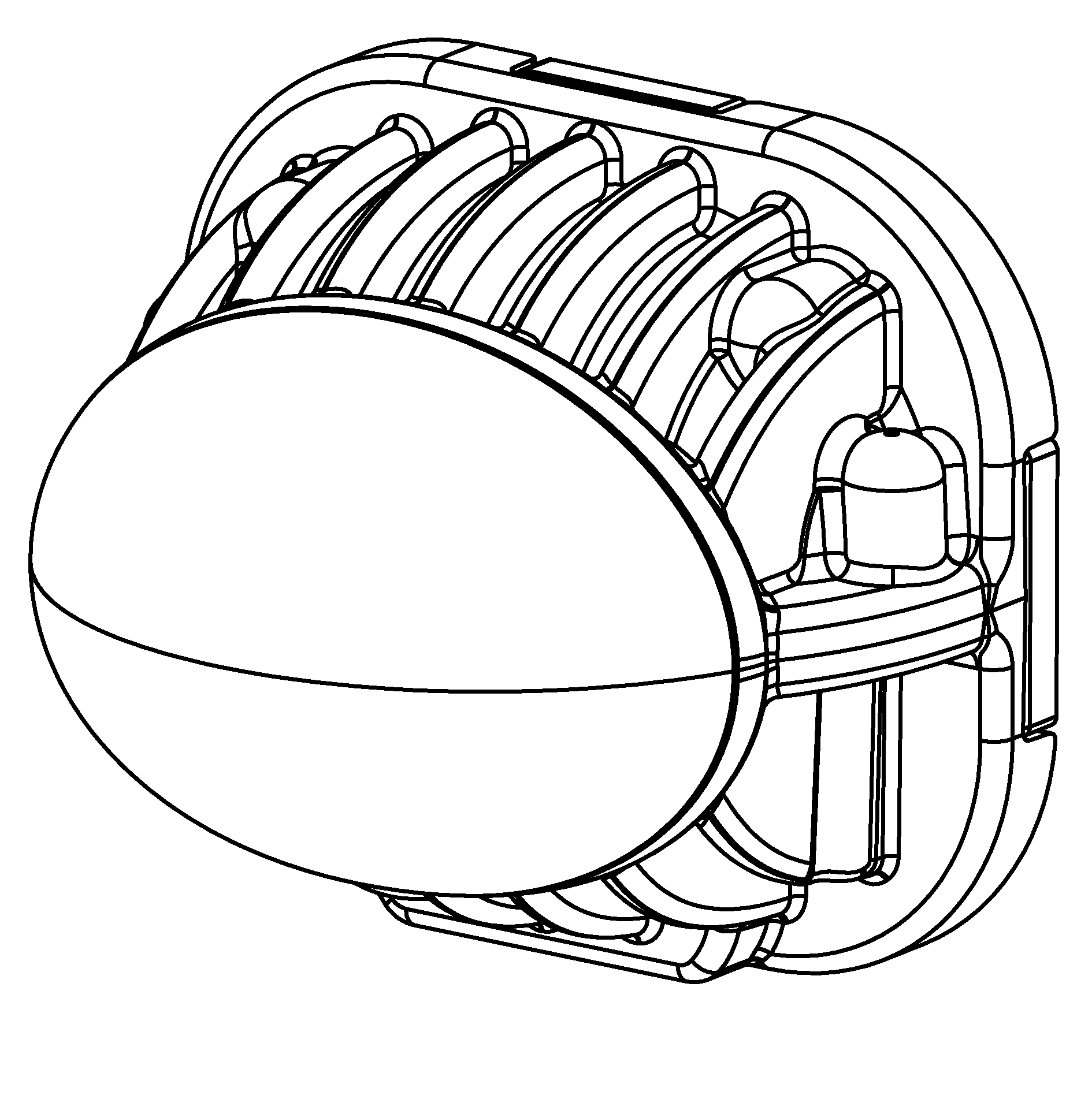
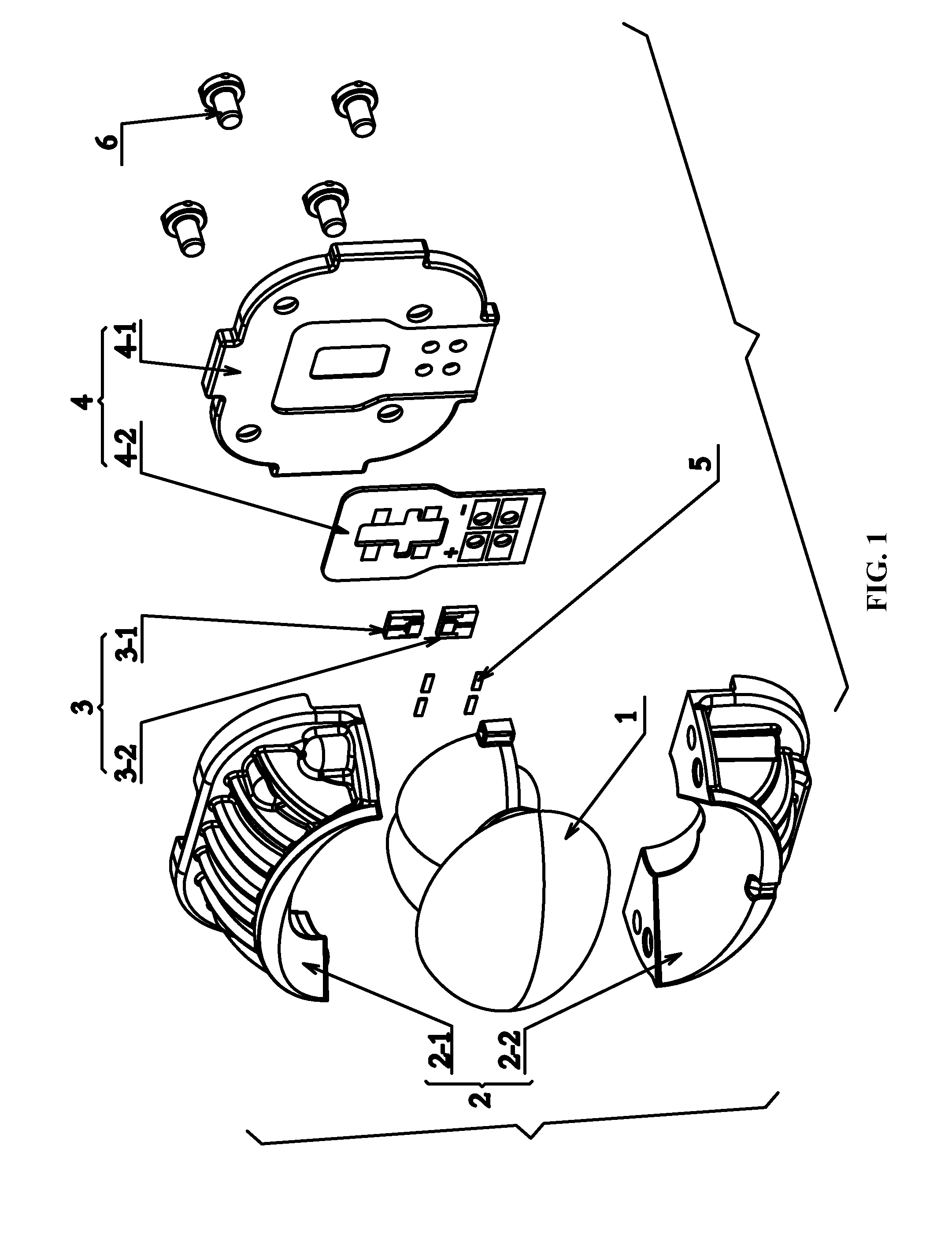
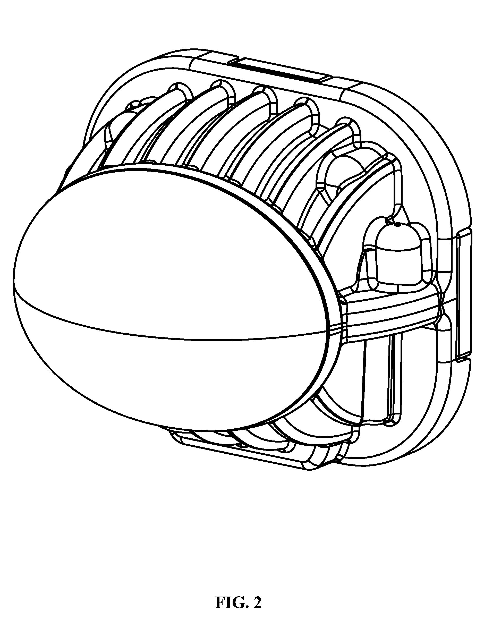
[0045]Referring to the drawings attached hereto, an LED optical assembly of an automotive lamp mainly comprises a lens 1, a lens frame 2, a LED light source 3, a light source frame assembly 4, and other supporting parts like electrodes 5 and screws 6 and so on. As for the structure of the assembly, please refer to FIGS. 1 and 2. Referring to FIG. 3, a main lens f which has non-rotational and non-spherical curved surfaces is positioned in front of the lens. The design principles and method of the main lens are the same as those disclosed by the prior art. When the refractive index of lens material stands between 1.4-2.4 as shown in FIGS. 3 and 4, the measurement value range of each point on the curved surface of the main lens fat the 3 co...


PUM


Abstract

An LED optical assembly for automotive low-beam headlamps, including: a lens, a lens frame, a light source frame assembly, and an LED light source. The lens includes a main lens and a plurality of reflectors. The main lens is located in the front of the LED optical assembly and the reflectors are scattered therearound. At one side of the main lens, four sets of the reflectors, which are symmetrical in shape, are respectively disposed at the left part and the right part thereof, and in a back of the main lens, six sets of the reflectors, which are symmetrical in shape, are respectively disposed at the left part and the right part thereof.

Description

CROSS-REFERENCE TO RELATED APPLICATIONS[0001]This application is a continuation-in-part of International Patent Application No. PCT / CN2011 / 076926 with an international filing date of Jul. 6, 2011, designating the United States, now pending, and further claims priority benefits to Chinese Patent Application No. 201120183147.0 filed Jun. 2, 2011, and to Chinese Patent Application No. 201110146966.2 filed Jun. 2, 2011. The contents of all of the aforementioned applications, including any intervening amendments thereto, are incorporated herein by reference.CORRESPONDENCE ADDRESS[0002]Inquiries from the public to applicants or assignees concerning this document should be directed to: MATTHIAS SCHOLL P. C., ATTN.: DR. MATTHIAS SCHOLL ESQ., 14781 MEMORIAL DRIVE, SUITE 1319, HOUSTON, TX 77079.BACKGROUND OF THE INVENTION[0003]1. Field of the Invention[0004]The invention relates to an automotive lighting system, and more particularly to an LED optical assembly for automotive low-beam headlamp...

Claims


Application Information

Patent Timeline
Patent Type & Authority Applications(United States)
IPC IPC(8): B60Q1/04
CPCF21S48/1154F21S48/1358F21S48/1388F21S48/1258F21S41/192F21S41/143F21S41/26F21S41/321F21S41/334F21S41/36F21S41/60F21S41/663F21S45/47F21S41/365F21S45/48
Inventor CHENG, XINGHUA
Owner TIANJIN FONCOL SCI & TECH DEV
Why Eureka
Try Eureka