Organic electroluminescence display device

Inactive Publication Date: 2012-02-16
CANON KK
View PDF3 Cites 2 Cited by
  • Summary
  • Abstract
  • Description
  • Claims
  • Application Information

AI Technical Summary

Benefits of technology

[0006]The present invention provides a display device with wide radiation angle chara

Problems solved by technology

One problem concerning organic EL devices, such as organic light-emitting diodes (OLEDs), is low light extraction efficiency.
In these terms, the extraction efficiency of an organic EL device is low because, since light is emitted at various angles from a light emitting layer in the organic EL device, total reflection components often appea

Method used


Image

  • Organic electroluminescence display device
  • Organic electroluminescence display device
  • Organic electroluminescence display device

Examples


Example

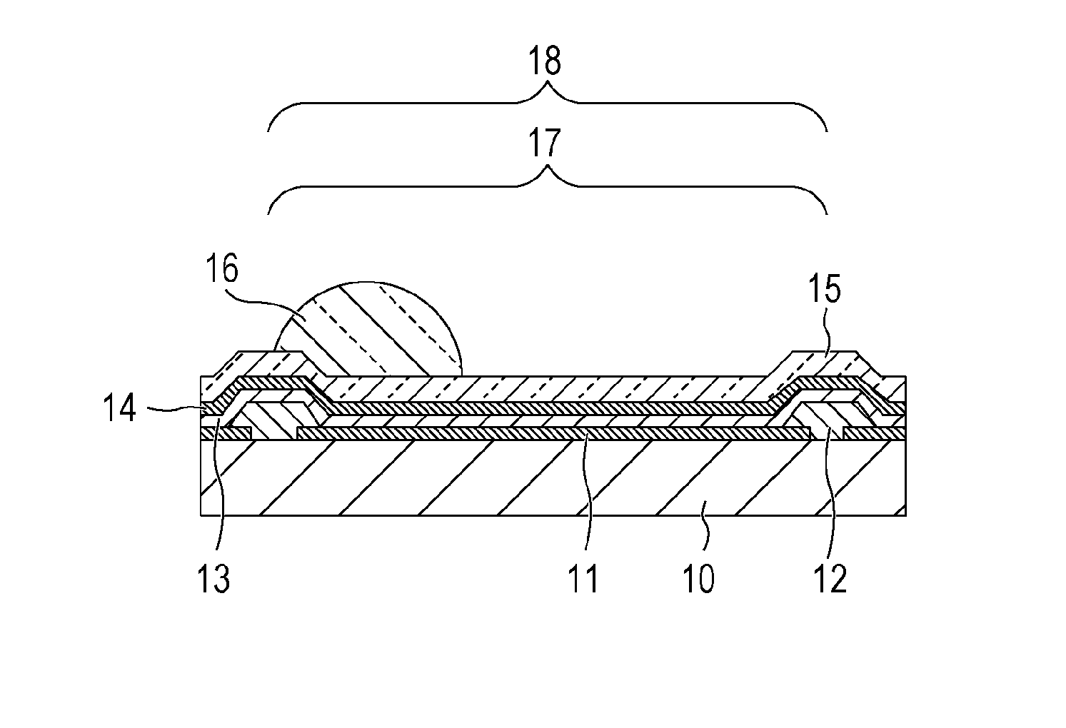
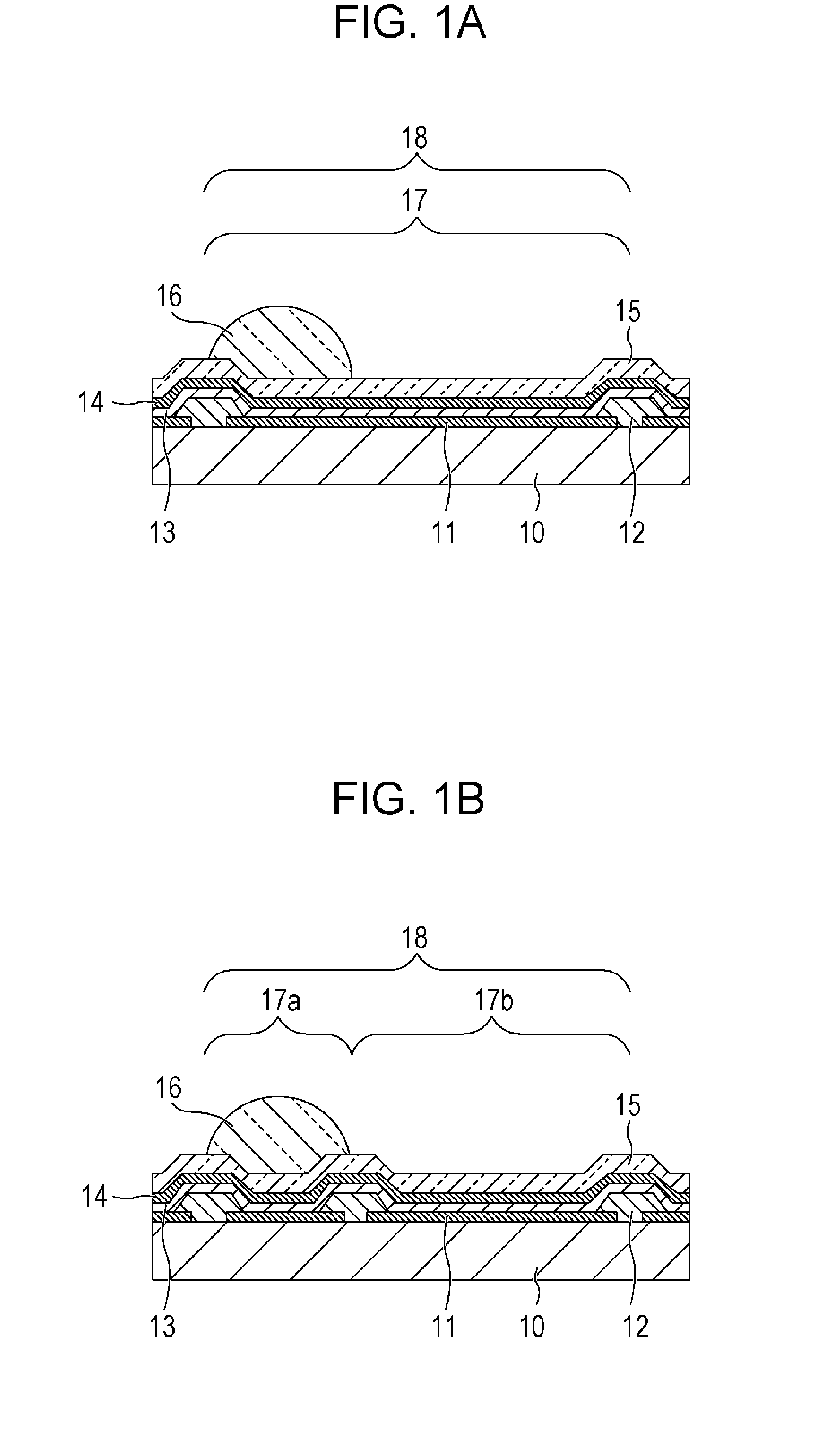
[0020]An organic electroluminescence display device (an organic EL display device) according to the present invention includes a plurality of pixels each of which includes an organic electroluminescence device (an organic EL device) and a lens. Each pixel includes a light emitting region provided with a lens and a light emitting region provided with no lens. An area of the light emitting region provided with a lens is smaller than that of the light emitting region provided with no lens. The present invention is embodied in the following two configurations in terms of correspondence relationship between the lens and the organic EL device.

[0021]In a first form, a single pixel is constituted by a single organic EL device; each organic EL device includes a light emitting region provided with a lens and a light emitting region provided with no lens.

[0022]In a second form, a single pixel includes a plurality of organic EL devices which emit the same colored light; one of the plurality of ...


PUM


Abstract

An organic electroluminescence display device includes a plurality of pixels each of which includes at least one organic electroluminescence device and a lens. Each pixel includes a light emitting region provided with a lens and a light emitting region provided with no lens. An area of the light emitting region provided with a lens is smaller than an area of the light emitting region provided without a lens.

Description

BACKGROUND OF THE INVENTION[0001]1. Field of the Invention[0002]The present invention relates to a display device incorporating an organic electroluminescence (EL) device and, more particularly, to a display device incorporating an organic EL device capable of enhancing light utilization efficiency from the top of the display device.[0003]2. Description of the Related Art[0004]One problem concerning organic EL devices, such as organic light-emitting diodes (OLEDs), is low light extraction efficiency. Light extraction efficiency may be generally defined as the fraction of light radiated outside of the organic EL device out of the total optical power generated in the active layer (light-emitting layer) of the organic EL device. In these terms, the extraction efficiency of an organic EL device is low because, since light is emitted at various angles from a light emitting layer in the organic EL device, total reflection components often appear at the interface between a protective layer...

Claims


Application Information

Patent Timeline
IPC IPC(8): H01J1/62
CPCH01L51/5275H10K50/858
Inventor MORIYAMA, TAKASHISHIKINA, NORIYUKISATO, NOBUHIKO
Owner CANON KK
Why Eureka
Try Eureka