Reflective liquid crystal projector and image reproduction apparatus

Inactive Publication Date: 2009-06-25
SONY CORP
View PDF10 Cites 14 Cited by
  • Summary
  • Abstract
  • Description
  • Claims
  • Application Information

AI Technical Summary

Benefits of technology

[0026]Further, since laser light is used as illuminating light, the light utilization efficiency is improved. Further, black display is implemented not by turning off the laser light beams of the colors but by intercepting a corresponding display unit of the liquid crystal layer composed of pixels for red, green and blue by means of a liquid crystal driving circuit. Therefore, the image contrast does not drop.
[0027]Further, unlike the laser scanning system disclosed in Patent Document 4, image light modulated by the liquid crystal panel is projected in an enlarged scale as divergent light

Problems solved by technology

Nevertheless, the limit to reduction of the size of the entire projector is such a size that the projector can be placed on the “palm of the hand”, and it is difficult to build the projector in a small-sized apparatus such as a portable telephone terminal.
Moreover, as pointed out also in Patent Document 3 (Japanese Patent Appl

Method used


Image

  • Reflective liquid crystal projector and image reproduction apparatus
  • Reflective liquid crystal projector and image reproduction apparatus
  • Reflective liquid crystal projector and image reproduction apparatus

Examples


first embodiment

1. First Embodiment

(Single Plate Type): FIGS. 1 to 10

[0042]As a first embodiment, a case of a single plate type which uses a single reflective liquid crystal panel for the three colors of red, green and blue is described.

[0043](1-1. First Example: FIGS. 1 to 6)

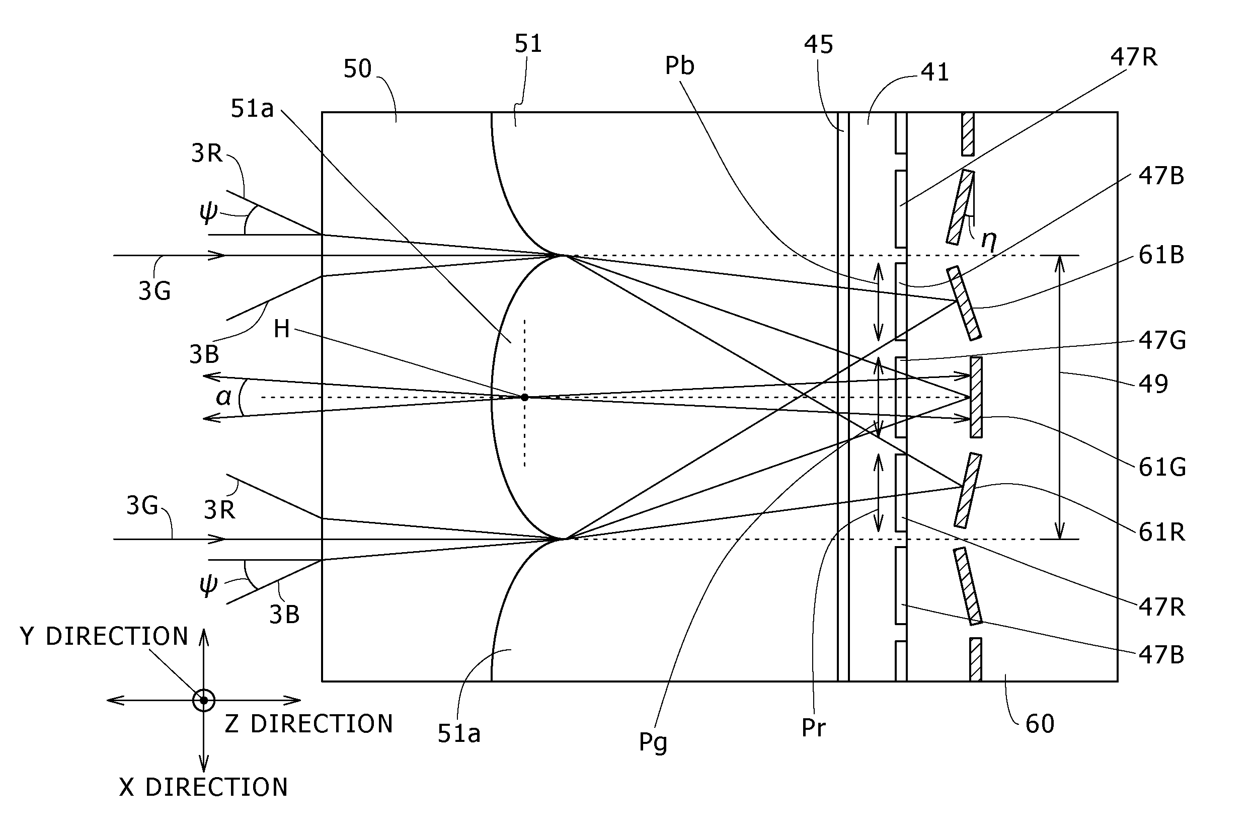
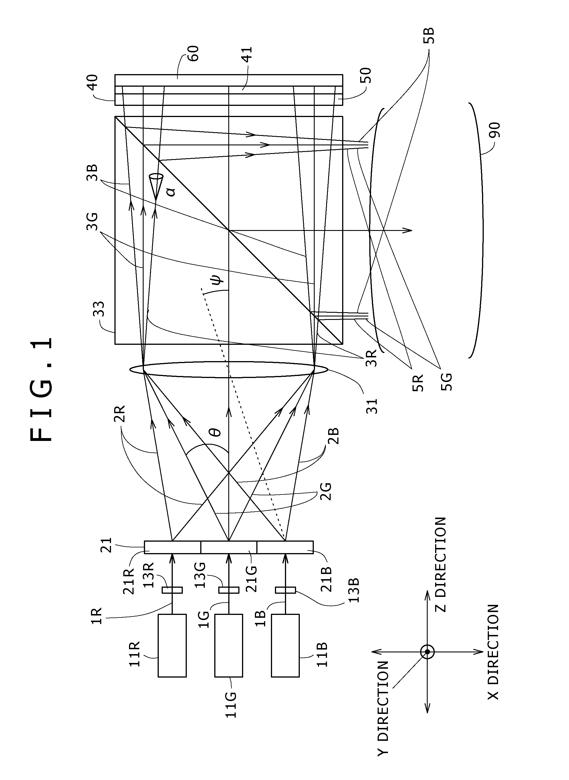
[0044]FIG. 1 shows a case wherein a diffractive optical device is used as a light beam diffusing and shaping optical device as a first example of a reflective liquid crystal projector of the single plate type.

[0045]In order to make directions definite, an X direction, a Y direction and a Z direction are defined as shown in the figure. The Y direction is, in FIG. 1, a direction perpendicular to the plane of the figure.

[0046]

[0047]In the present example, a red laser 11R, a green laser 11G and a blue laser 11B are provided and arrayed in the X direction.

[0048]For each of the red laser 11R and the blue laser 11B, a semiconductor laser is used. For example, for the red laser 11R, a laser of the InGaAsP-based type or the InAlGaP-bas...

second embodiment

2. Second Embodiment

(Double-Plate Type): FIG. 11

[0147]As a second embodiment, an example of a reflective liquid crystal projector of the double plate type which uses two reflective liquid crystal panels for the three colors of red, green and blue is shown in FIG. 11.

[0148]In the present example, the red laser light beam 1R emitted from the red laser 11R formed from a semiconductor laser and the blue laser light beam 1B emitted from the blue laser 11B formed from a semiconductor laser are introduced to the refractive optical device 23 after the cross sectional shape thereof is changed so as to approach a circular shape as described above by collimation lenses 15R and 15B, respectively. Meanwhile, the green laser light beam 1G emitted from the green laser 11G formed from a DPSS laser is introduced to the refractive optical device 23 after the beam diameter thereof is increased as described above by a beam expander 17G.

[0149]In this instance, the lasers 11R, 11G and 11B are arranged su...

third embodiment

3. Third Embodiment

(Triple-Plate Type): FIG. 12

[0160]As a third embodiment, an example of a reflective liquid crystal projector of the triple plate type wherein individual reflective liquid crystal panels from each other are used for the three colors of red, green and blue is shown in FIG. 12.

[0161]In the present example, after the cross sectional shape of red and blue laser light beams emitted from the red laser 11R and the blue laser 11B is changed so as to approach a circular shape by refractive optical devices 23R and 23B, respectively, the red and blue laser light beams are diffused and shaped by the refractive optical devices 23R and 23B such that they are introduced to the pixels over the overall area of the display region of reflective liquid crystal panels 40R and 40B. Meanwhile, the green laser light beam emitted from the green laser 11G is, after the beam diameter thereof is increased by the beam expander 17G, diffused and shaped by a refractive optical device 23G such th...


PUM


Abstract

It is an object of the present invention to miniaturize a reflective liquid crystal projector to such a degree that it can be built in a small-sized apparatus such as a portable telephone terminal.
Laser light beams (1R), (1G), (1B) are diffused and shaped by diffractive optical devices (21R), (21G), (21B) such that they are introduced to corresponding pixels of a liquid crystal layer (41) over an overall area of a display region of a reflective liquid crystal panel (40).
The diffused and shaped laser light beams (2R), 2(G), 2(B) are introduced to the reflective liquid crystal panel (40) through a field lens (31) and a polarizing beam splitter (33). Red, green and blue pixels are formed on the reflective liquid crystal panel (40), and a microlens array is formed on an incoming and outgoing side substrate (50) while reflecting layers corresponding to the pixels are formed on a reflection side substrate (60). The laser light fluxes of the colors are distributed and condensed by the microlenses and introduced to the corresponding pixels and then reflected by the corresponding reflecting layers.
Also it is possible to use refractive optical devices in place of the diffractive optical devices.

Description

TECHNICAL FIELD[0001]This invention relates to a reflective liquid crystal projector and an image reproduction apparatus such as a portable telephone terminal, a digital camera, a video camera, a personal computer, a game machine or a toy wherein a reflective liquid crystal panel is used as a light valve.BACKGROUND ART[0002]While, as liquid crystal projectors (projectors wherein a liquid crystal panel is used as a light valve), those which use a transmissive liquid crystal panel and those which use a reflective liquid crystal panel are available, it is considered that conventionally liquid crystal projectors of both types are usually installed and used in a house and the like. As disclosed in Patent Document 1 (Japanese Patent Application Laid-Open No. Sho 63-118125) or Patent Document 2 (Japanese Patent Application Laid-Open No. Hei 4-60538), a lamp such as a metal halide lamp, a high-pressure mercury lamp or a xenon lamp is used as the light source.[0003]However, where a lamp is u...

Claims


Application Information

Patent Timeline
IPC IPC(8): G02F1/1335
CPCG02F1/133553G02F2203/34H04N9/3161H04N9/3129G03B21/2033G03B21/00G02F1/13
Inventor KAISE, KIKUO
Owner SONY CORP
Why Eureka
Try Eureka