
Display device

Inactive Publication Date: 2019-07-25
INNOLUX CORP
View PDF5 Cites 0 Cited by
  • Summary
  • Abstract
  • Description
  • Claims
  • Application Information

AI Technical Summary

Benefits of technology

The objective of this patent is to improve the efficiency of a display device's light utilization.

Problems solved by technology

However, the light absorption of the color filter layer decreases the light utility efficiency, and the color saturation is also an issue for the display device with the color filter layer.

Method used


Image

  • Display device
  • Display device
  • Display device

Examples


Embodiment Construction

[0017]The present disclosure may be understood by reference to the following detailed description, taken in conjunction with the drawings as described below. It is noted that, for purposes of illustrative clarity and being easily understood by the readers, various drawings of this disclosure show a portion of the display device, and certain elements in various drawings may not be drawn to scale. In addition, the number and dimension of each device shown in drawings are only illustrative and are not intended to limit the scope of the present disclosure.

[0018]Certain terms are used throughout the description and following claims to refer to particular components. As one skilled in the art will understand, electronic equipment manufacturers may refer to a component by different names. This document does not intend to distinguish between components that differ in name but not function. In the following description and in the claims, the terms “include”, “comprise” and “have” are used in...


PUM


Abstract

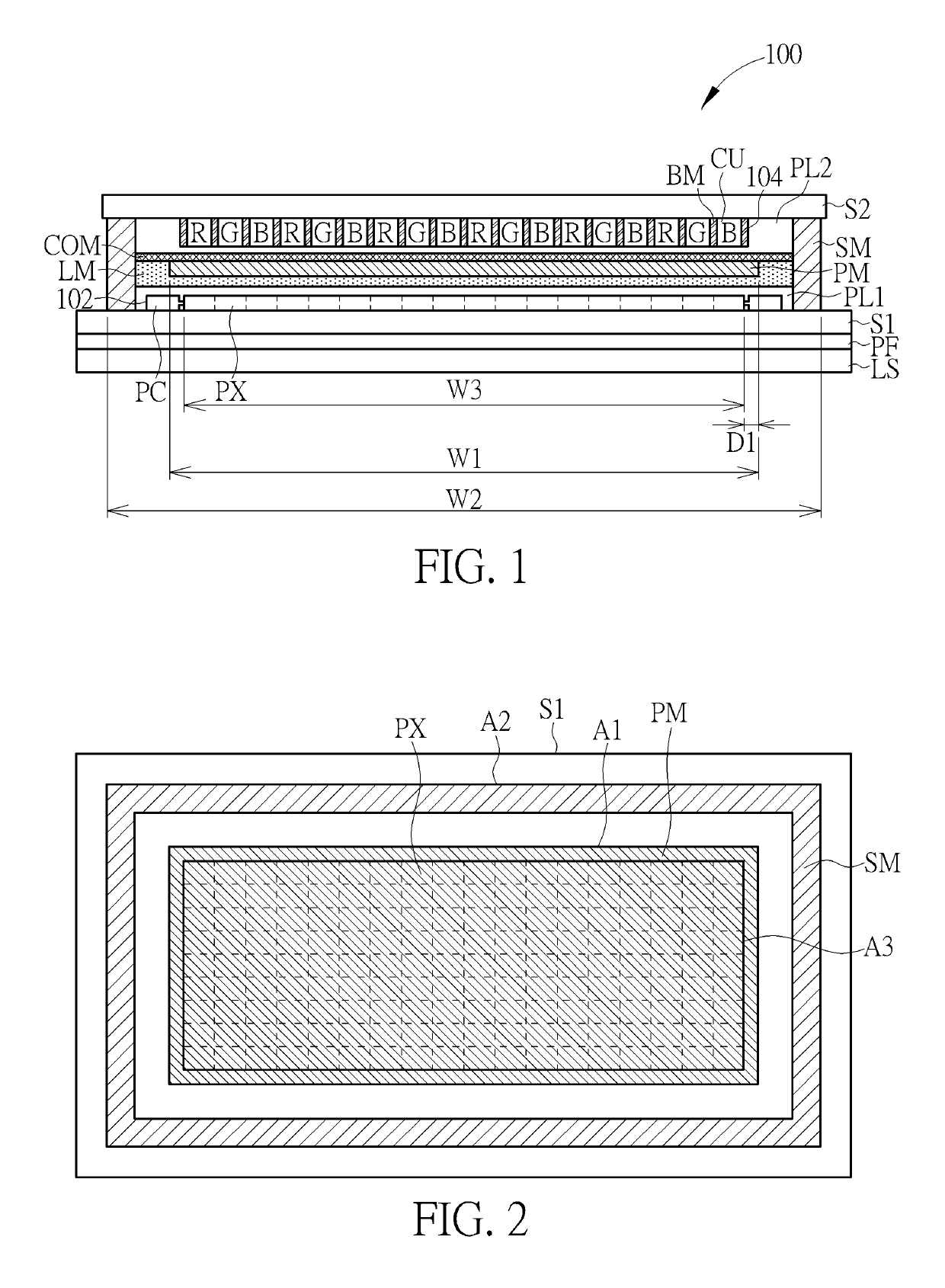
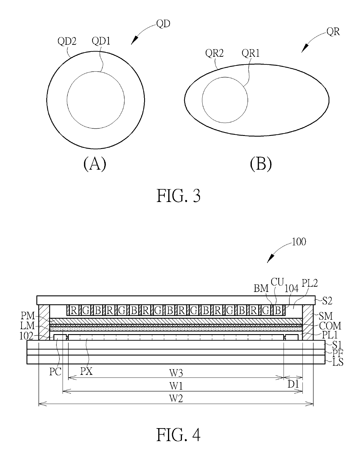
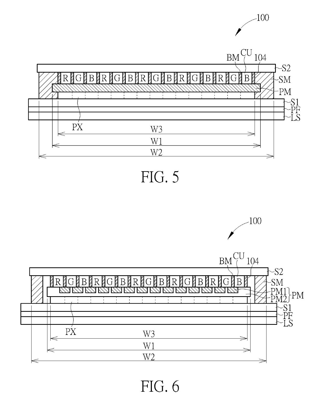
A display device includes a first substrate, a second substrate, a plurality of pixels, a polarizing member, and a sealing member. The plurality of pixels are disposed between the first substrate and the second substrate. The polarizing member is disposed between the plurality of pixels and the second substrate, wherein a first area is defined by the polarizing member. The sealing member is disposed between the first substrate and the second substrate, wherein a second area is defined by the sealing member. The first area is located within the second area.

Description

BACKGROUND OF THE DISCLOSURE1. Field of the Disclosure[0001]The present disclosure relates to a display device, and more particularly, to a display device including a polarizing member.2. Description of the Prior Art[0002]Nowadays, display devices have advantages of portability, low power consumption, and low radiation. Therefore, they are widely used in various information products, such as desktop computers, notebooks, smart phones, car displays and head up displays.[0003]Conventionally, in order to provide different color light for different pixels, a color filter layer is disposed in the display device, which permits specific color lights with predetermined wavelength ranges to pass through but absorbs other color lights that are out of the predetermined wavelength ranges in individual pixels, so as to display colorful images. However, the light absorption of the color filter layer decreases the light utility efficiency, and the color saturation is also an issue for the display ...

Claims


Application Information

Patent Timeline
IPC IPC(8): G02F1/1335G02F1/1339G02F1/1362
CPCG02F1/133533G02F1/1339G02F1/136286G02F1/133514G02F2001/133565G02F2001/133548G02F1/1368G02F2202/108G02F1/133617G02F1/133528G02F1/1336G02F1/133614G02F1/1362G02B5/3025G02B5/3058G02B5/206G02B5/208G02F1/133548G02F1/133565G02B5/28G02B5/283G02F1/01791
Inventor CHEN, JIA-YUANTSAI, TSUNG-HANLEE, KUAN-FENGHSU, PING-CHIEH
Owner INNOLUX CORP
Learn More