Light source device and projection - type display device using same

a technology of projection-type display and light source device, which is applied in the field of projection, can solve the problems of limited amount of light for augmenting an insufficient color by leds, optical loss, and insufficient light utilization efficiency of light source device, and achieve the effect of raising light utilization efficiency

Active Publication Date: 2012-07-19
NEC CORP
View PDF17 Cites 14 Cited by
  • Summary
  • Abstract
  • Description
  • Claims
  • Application Information

AI Technical Summary

Benefits of technology

[0032]It is therefore an object of the present invention to provide: a light source device that can raise the light utilization efficiency when mixing colors and thus solve the above-described problem, and a projection-type display device that is provided with the light source device.

Problems solved by technology

As shown in Patent Document 1 or Patent Document 2, when auxiliary illumination light is used to augment brightness, the light utilization efficiency is not necessarily improved due to not only the non-use of the original light that was replaced, but also the occurrence of optical loss during replacement.
On the other hand, in Patent Document 3 in which the difference in polarization or wavelength is used to synthesize light, light of each of the colors is irradiated and synthesized from one direction, whereby the amount of light for augmenting an insufficient color by LEDs is limited and light cannot be augmented efficiently.

Method used


Image

  • Light source device and projection - type display device using same
  • Light source device and projection - type display device using same
  • Light source device and projection - type display device using same

Examples


first exemplary embodiment

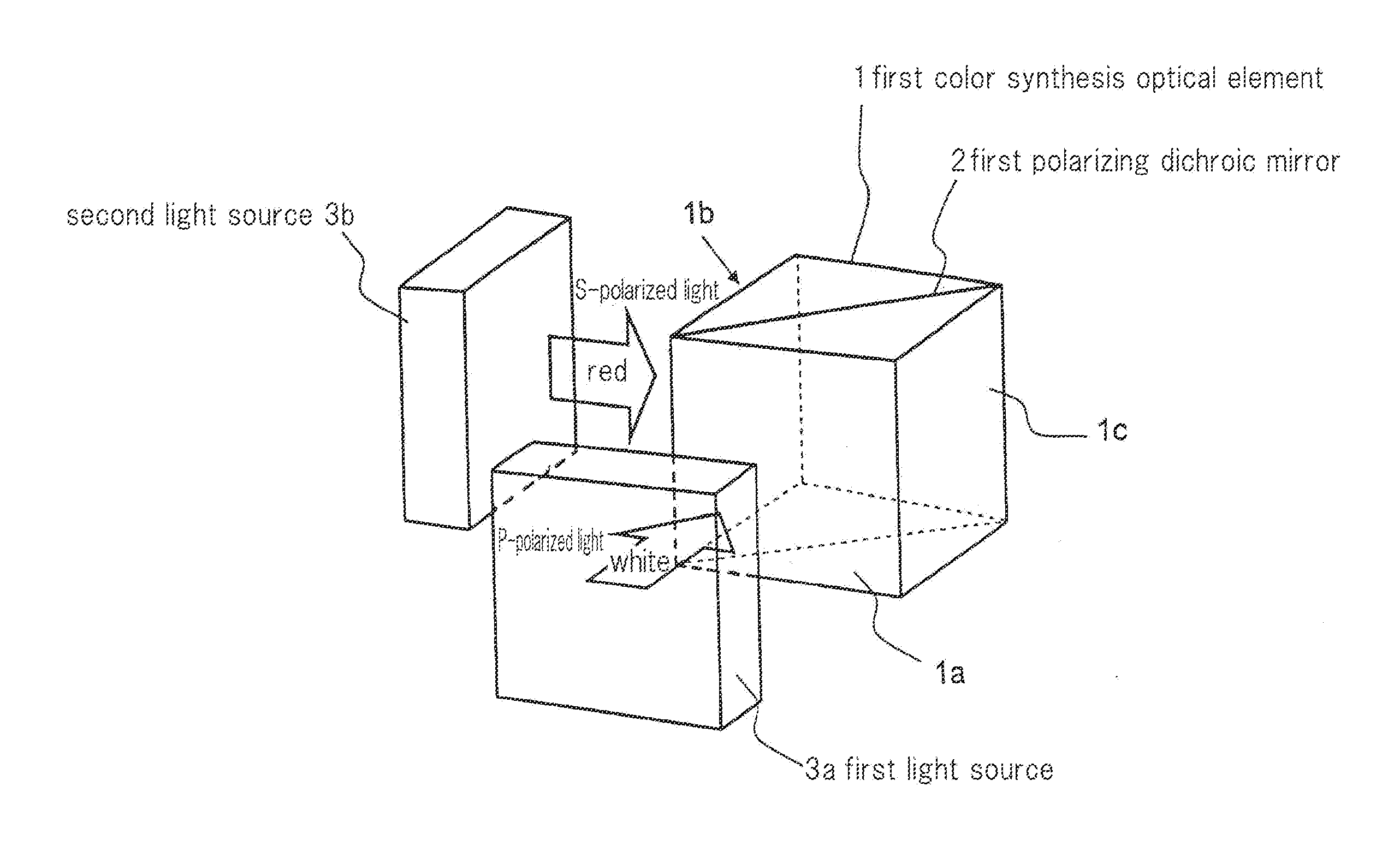
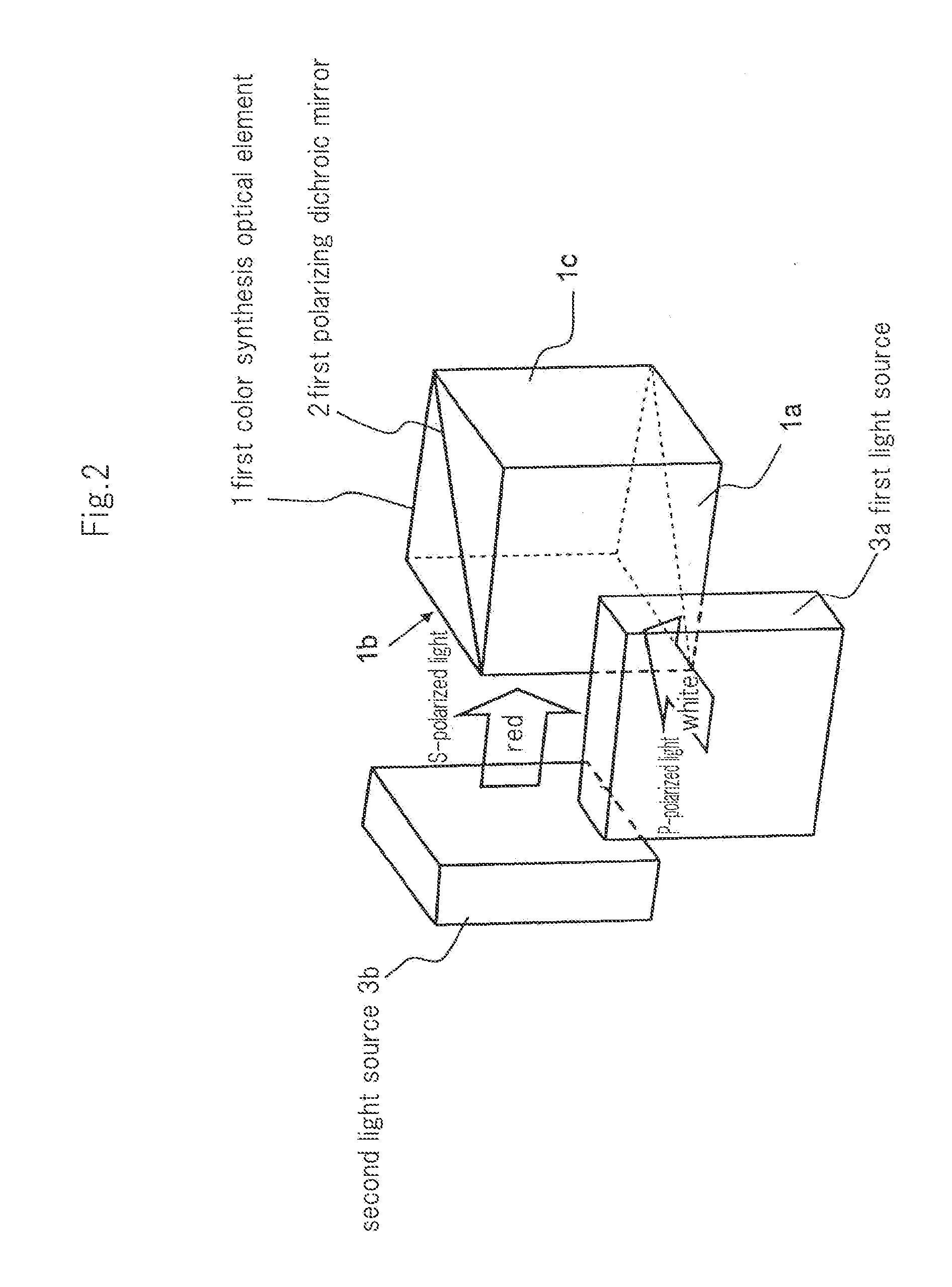
[0090]FIG. 2 is a perspective view showing the configuration of the light source device that is the first exemplary embodiment of the present invention.

[0091]Referring to FIG. 2, the light source device includes first color synthesis optical element 1, first light source 3a, and second light source 3b.

[0092]First color synthesis optical element 1 is a polarizing dichroic prism composed of two right angle prisms in which oblique sides are joined to each other. First polarizing dichroic mirror 2 composed of a dielectric multilayer film is formed on the junction surfaces of the two right angle prisms.

[0093]Of the four side surfaces of first color synthesis optical element 1, two adjacent side surfaces are incident surfaces 1a and 1b, and the side surface opposite incident surface 1b is exit surface 1c. First light source 3a is disposed to face incident surface 1a, and second light source 3b is disposed to face incident surface 1b.

[0094]First light source 3a emits white light (P-polar...

second exemplary embodiment

[0117]FIG. 7 is a perspective view showing the configuration of the light source device that is the second exemplary embodiment of the present invention.

[0118]Referring to FIG. 7, the light source device includes first color synthesis optical element 1, second color synthesis optical element 11, first light source 3a, second light source 3b, and third light source 3c. First color synthesis optical element 1, first light source 3a, and second light source 3b are the same as the components shown in FIG. 2. Second color synthesis optical element 11 is arranged in the direction of progression of light that is exited from exit surface 1c of first color synthesis optical element 1.

[0119]Second color synthesis optical element 11 is a polarizing dichroic prism composed of two right angle prisms in which the oblique sides are joined together. Second polarizing dichroic mirror 12 composed of a dielectric multilayer film is formed on the junction surfaces of the two right angle prisms.

[0120]Of...

third exemplary embodiment

[0146]FIG. 13 is a perspective view showing the configuration of the light source device that is the third exemplary embodiment of the present invention.

[0147]Referring to FIG. 13, the light source device includes first color synthesis optical element 1, second color synthesis optical element 11, third color synthesis optical element 21, first light source 3a, second light source 3b, third light source 3c, and fourth light source 3d.

[0148]First color synthesis optical element 1, second color synthesis optical element 11, first light source 3a, second light source 3b, and the third light source are identical to the elements shown in FIG. 7. Third color synthesis optical element 21 is arranged in the direction of progression of light that is exited from exit surface 11 c of second color synthesis optical element 11.

[0149]Third color synthesis optical element 21, similar to first color synthesis optical element 1 and second color synthesis optical element 11, is a polarizing dichroic ...


PUM


Abstract

A light source device includes: a first light source (3a) that emits first polarized light of a plurality of colors including different wavelengths; a second light source (3b) that emits second polarized light whose polarization state differs from that of the first polarized light and that includes light of at least one color from among the plurality of colors; and a first color synthesis optical element (1) that synthesizes the first polarized light emitted from the first light source (3a) and the second polarized light emitted from the second light source (3b).

Description

TECHNICAL FIELD [0001]The present invention relates to a projection-type display device of which a projector is representative, and more particularly relates to a light source device that produces an illumination light in which light of a plurality of colors is synthesized, and to a projection-type display device that uses this light source device.BACKGROUND ART [0002]A projection-type display device includes a light source device, display elements that are irradiated by illumination light from the light source device, and a projection lens that enlarges and projects the images displayed on the display elements onto a screen.[0003]Projection-type display devices can be broadly divided between two types.[0004]The first type of projection-type display device is made up of: a white light source; a plurality of dichroic mirrors that split white light into luminous flux of the three primary colors of red (R), green (G), and blue (B); three liquid crystal display elements that are irradia...

Claims


Application Information

Patent Timeline
Patent Type & Authority Applications(United States)
IPC IPC(8): G03B21/14F21V9/14
CPCG03B21/2033G03B33/06G03B33/12G03B21/14G03B21/2073G02B27/10H04N9/3105H04N9/3167G02B5/04G03B21/2013G03B21/2066
Inventor IMAI, MASAOSAITOH, GOROHOKUMURA, FUJIO
Owner NEC CORP
Why Eureka
Try Eureka