Luminous keyboard device

a keyboard and luminous technology, applied in the field of keyboard devices, can solve the problems of increased cost, reduced luminous efficiency, and drawbacks, and achieve the effect of enhancing luminous efficiency and reducing thickness

Active Publication Date: 2015-04-23
PRIMAX ELECTRONICS LTD
View PDF8 Cites 16 Cited by
  • Summary
  • Abstract
  • Description
  • Claims
  • Application Information

AI Technical Summary

Benefits of technology

[0012]An object of the present invention provides a luminous keyboard device with reduced thickness and enhanced luminous efficiency.
[0013]Another object of the present invention also provides a luminous keyboard device with enhanced light utilization efficiency.
[0016]The luminous keyboard device of the present invention utilizes thicker light-emitting elements. Consequently, the luminous efficiency of the light beams from the light-emitting elements will be enhanced. Moreover, the supporting plate comprises plural receiving part for accommodating the thicker light-emitting elements. The reflective layer, the light-shading plate or the reflecting plate is disposed around the light-emitting elements for reflecting the light beams that are emitted by the light-emitting elements. Consequently, the light beams can be introduced into the light guide plate and directed to the plural light-outputting zones of the keypad module. Under this circumstance, the luminous efficiency of the luminous keyboard device is slightly increased. Moreover, since the light beams emitted by the light-emitting elements are not leaked out, the light utilization efficiency is further enhanced. Moreover, the luminous keyboard device of the present invention may use a thinner light guide plate in order to meet the requirement of slimness. Moreover, the uses of the thicker light-emitting elements can increase the luminous efficiency and reduce the cost.

Problems solved by technology

However, some drawbacks may occur.
For example, the luminous efficiency of a thinner light-emitting element (e.g. the light-emitting element having a thickness smaller than 0.3 mm) is lower than a thicker light-emitting element (e.g. the light-emitting element having a thickness of 0.4 mm or 0.6 mm), and the thinner light-emitting element is more expensive than the thicker light-emitting element.
In other words, the conventional luminous keyboard device with the thinner light-emitting element has reduced luminous efficiency and increased cost.
Under this circumstance, the light utilization efficiency is insufficient.

Method used


Image

  • Luminous keyboard device
  • Luminous keyboard device
  • Luminous keyboard device

Examples


first embodiment

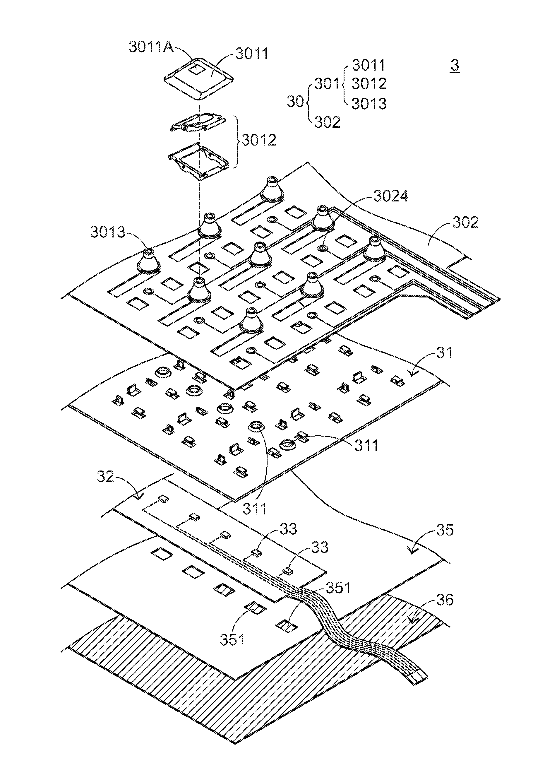
[0031]The structure of the switch circuit member 302 will be illustrated in more details as follows. FIG. 5 is a schematic exploded view illustrating the switch circuit member of the luminous keyboard device according to the present invention. In this embodiment, the switch circuit member 302 comprises an upper wiring board 3021, a spacer layer 3022 and a lower wiring board 3023. The upper wiring board 3021 has plural upper contacts 3021A. The spacer layer 3022 is disposed under the upper wiring board 3021. Moreover, the spacer layer 3022 comprises plural perforations 3022A corresponding to the plural upper contacts 3021A. The lower wiring board 3023 is disposed under the spacer layer 3022. Moreover, the lower wiring board 3023 comprises plural lower contacts 3023A corresponding to the plural upper contacts 3021A. The plural upper contacts 3021A, the plural perforations 3022A and the plural lower contacts 3023A are collectively defined as plural key switches 3024. When the switch ci...

second embodiment

[0042]Hereinafter, the relationships between the keycap 4011, the frame body 4012 and the connecting element 4013 will be illustrated with reference to FIGS. 6 and 8. FIG. 8 is a schematic partial perspective view illustrating the keycap, the frame body and the connecting element of the luminous keyboard device according to the present invention. In FIG. 8, the structures of the keycap 4011, the frame body 4012 and the connecting element 4013 are shown. The first magnetic element 4014 is disposed on a bottom surface 4011B of the keycap 4011, and located at a first side of the keycap 4011. The second magnetic element 4015 is disposed on a first sidewall 4013A of the connecting element 4013, and located near the first magnetic element 4014. The first magnetic element 4014 and the second magnetic element 4015 are magnetically attracted by each other so as to generate a magnetic force. In response to the magnetic force, the keycap 4011 is returned to its original position. On the other ...


PUM


Abstract

A luminous keyboard device includes a keypad module, a supporting plate, a flexible circuit board, a light-emitting element, a reflective layer, and a light guide plate. The supporting plate includes plural receiving parts. The flexible circuit board is contacted with the plural receiving parts to form plural bent structures. The light-emitting element and the reflective layer are disposed on the flexible circuit board. When a light beam is emitted by the light-emitting element, the portion of the light beam that is not directed to the light guide plate is reflected back to the light guide plate by the reflective layer on the plural bent structures. Consequently, the amount of light introduced into the light guide plate increases.

Description

FIELD OF THE INVENTION[0001]The present invention relates to a keyboard device, and more particularly to a luminous keyboard device.BACKGROUND OF THE INVENTION[0002]Generally, the widely-used peripheral input device of a computer system includes for example a mouse device, a keyboard device, a trackball device, or the like. Via the keyboard device, characters and symbols can be inputted into the computer system directly. As a consequence, most users and most manufacturers of input devices pay much attention to the development of keyboard devices.[0003]FIG. 1 is a schematic top view illustrating the outer appearance of a conventional keyboard device. As shown in FIG. 1, there are plural keys 10 on a surface of the conventional keyboard device 1. These keys 10 are classified into several types, e.g. ordinary keys 101, numeric keys 102 and function keys 103. When one of these keys 10 is depressed by the user's finger, a corresponding signal is issued to the computer, and thus the compu...

Claims


Application Information

Patent Timeline
Patent Type & Authority Applications(United States)
IPC IPC(8): H01H13/83
CPCH01H13/83H01H3/125H01H2219/06H01H2219/062
Inventor CHEN, CHUNG-YUAN
Owner PRIMAX ELECTRONICS LTD
Why Eureka
Try Eureka