Optical Control Device Having Light Modulation Film

a technology of optical control device and light modulation film, which is applied in the direction of optics, identification means, instruments, etc., can solve the problems of difficult meeting of optical shutters using bulk plzt, many constraints on material selection, and insufficient effective display area, etc., to achieve the effect of improving light utilization efficiency

Inactive Publication Date: 2008-05-08
ROHM CO LTD
View PDF6 Cites 15 Cited by
  • Summary
  • Abstract
  • Description
  • Claims
  • Application Information

AI Technical Summary

Benefits of technology

[0028]An aspect of the present invention has been achieved in view of these circumstances, and an object thereof is to provide a reflection-type light control apparatus featuring an improved light utilization efficiency.

Problems solved by technology

However, it is difficult for the optical shutters using bulk PLZT to meet the demands for miniaturization or higher integration or the demands for lowered operating voltage or lowered cost.
Besides, the bulk method involves a process of treating at high temperatures of 1000° C. or above after the mixing of material metal oxides, and hence, if applied to a device forming process, it may place many constraints on the selection of materials, the structure of the device and the like.
In so doing, however, the structure as described in aforementioned Patent Document 3 has the problem that the area where the drive circuit is formed cannot be used as a display area and hence an effective display area cannot be secured sufficiently.
Also, when visible light is used as the irradiation light, a transmissive display apparatus as described above had the problem that the drive circuit cannot be formed on a silicon or like substrate which is opaque to visible light.
Moreover, with a display apparatus as described in Patent Document 3, which uses polarizing plates, a loss of light due to the polarizing plates occurs.
When an electrode using Au, IrO2, Al, or the like as material is formed on the surface of PLZT, the electrode part does not allow the penetration of light, so that the opening ratio and light utilization efficiency will drop inevitably.
However, it is difficult to form the film thickness of a PLZT film, which is so thin, with a high accuracy of about 1%.

Method used


Image

  • Optical Control Device Having Light Modulation Film
  • Optical Control Device Having Light Modulation Film
  • Optical Control Device Having Light Modulation Film

Examples


first embodiment

[0108]A light control apparatus according to a first embodiment will be described in outline. This light control apparatus is used, for instance, as a spatial light modulator SLM in a hologram recording / reproducing apparatus.

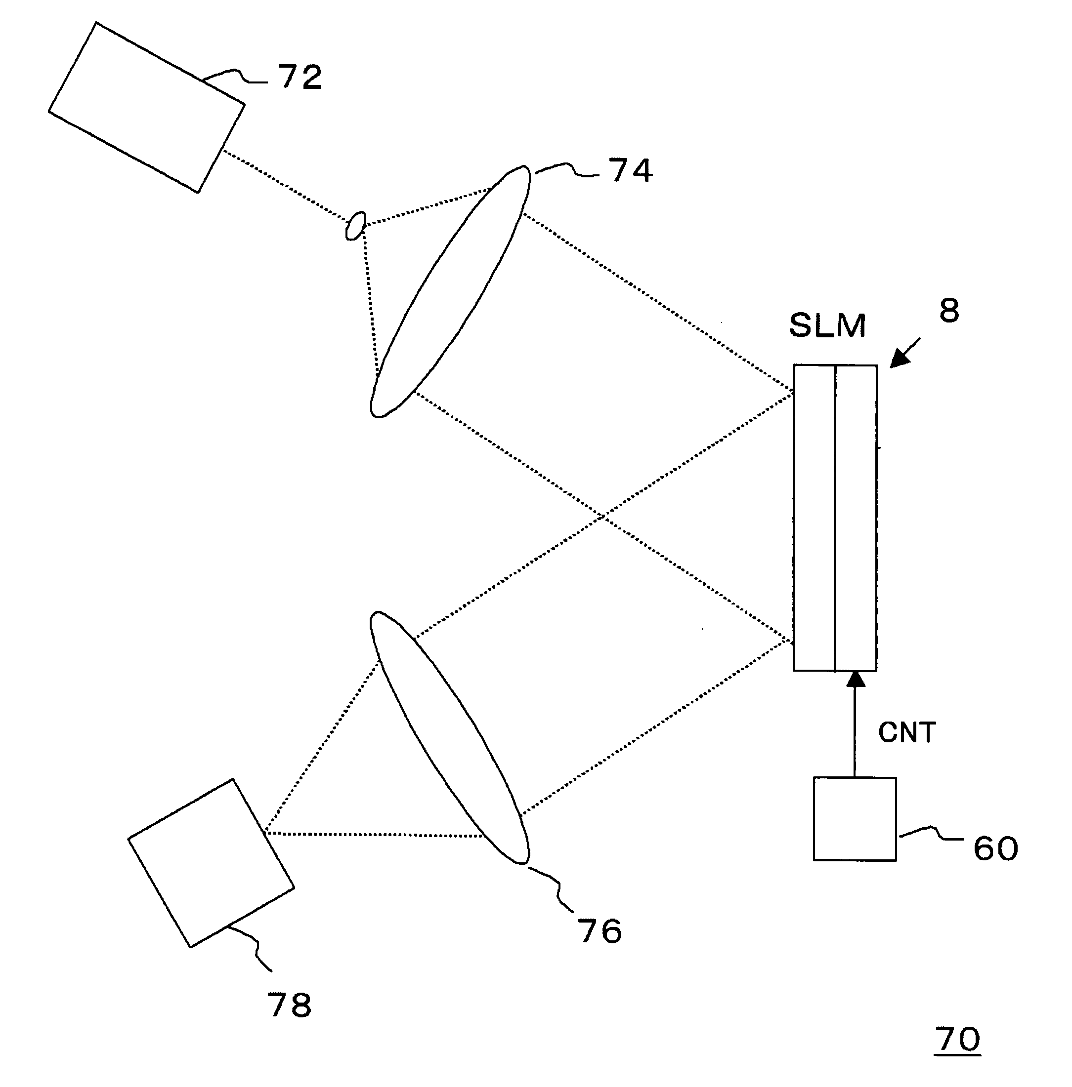
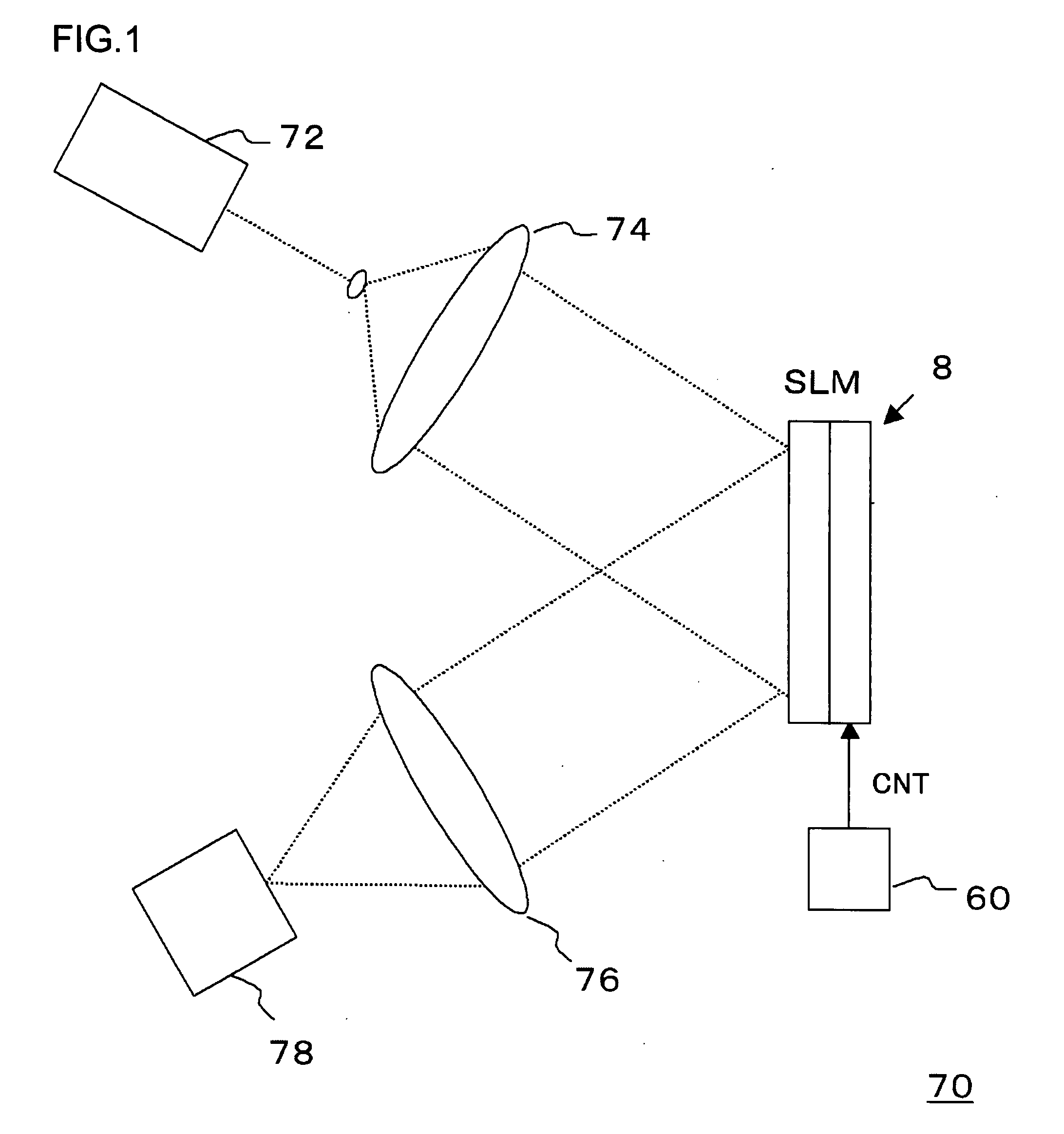
[0109]FIG. 1 is an illustration showing a hologram recording apparatus wherein a light control apparatus according to the present embodiment is used as a spatial light modulator SLM. The hologram recording apparatus 70 includes a control unit 60, a laser light source 72, a beam expander 74, a Fourier transform lens 76, and a recording medium 78.

[0110]In the hologram recording apparatus 70, laser light emitted from the laser light source 72 is split into two beams of light by a beam splitter (not shown). One of the beams of light, which is used as reference light, is led into recording medium 78. The other of the beams of light undergoes an enlargement of beam diameter by the beam expander 74 and is irradiated to a spatial light modulator SLM (light control appar...

second embodiment

[0157]A light control apparatus according to a second embodiment of the present invention will be described in outline. This light control apparatus is used, for instance, as a spatial light modulator in a hologram recording / reproducing apparatus.

[0158]FIG. 1 is an illustration showing a hologram recording apparatus wherein a light control apparatus according to the present embodiment is used as a spatial light modulator. The hologram recording apparatus 70 includes a spatial modulator SLM (light control apparatus 8), a control unit 60, a laser light source 72, a beam expander 74, a Fourier transform lens 76, and a recording medium 78.

[0159]In the hologram recording apparatus 70, laser light emitted from the laser light source 72 is split into two beams of light by a beam splitter (not shown). One of the beams of light, which is used as reference light, is led into recording medium 78. The other of the beams of light undergoes an enlargement of beam diameter by the beam expander 74 ...

third embodiment

[0222]A light control apparatus according to a third embodiment of the present invention will be described in outline. This light control apparatus is a light modulator which changes its reflectance by the application of voltage from outside. This light control apparatus, which has a Fabry-Perot resonator structure, is provided with a light modulating film, which has the refractive index changed by the electric field applied, and two reflection layers provided in such a way as to hold the light modulating film in between. The light control apparatus constitutes a light control system together with a laser light source and an optical system. Laser light is introduced into the light control apparatus at a predetermined incident angle. The laser light reflected by the light control apparatus has an intensity proportional to the reflectance of the light control apparatus, so that the reflected light can be put to a variety of applications by recording or detecting it by a recording medi...


PUM

PropertyMeasurementUnit
thicknessaaaaaaaaaa
thicknessaaaaaaaaaa
temperaturesaaaaaaaaaa

Abstract

A reflection-type light control apparatus featuring the improved light utilization efficiency is provided.
A light control apparatus is provided with a plurality of pixels arranged two-dimensionally on a substrate. A first reflection layer is formed on the substrate. A light modulating film is provided on the top surface of the first reflection layer. As material for this light modulating film, electro-optical material, such as PLZT, whose refractive index changes according to an electric field applied is selected. A transparent electrode is provided on the top surface of the light modulating film. A second reflection layer is formed on the top surface of the transparent electrode. This second reflection layer is formed of a dielectric multilayer film, which is a stack of alternating first dielectric film and second dielectric film having different refractive indices. The first reflection layer, the light modulating film and the second reflection layer constitute a resonator. The transparent electrode and the first reflection layer form a pair of electrodes, and control the reflectance of a light control apparatus by varying the electric field applied to the light modulating film.

Description

BACKGROUND OF THE INVENTION[0001]1. Field of the Invention[0002]This invention relates to a light control apparatus.[0003]2. Description of the Related Art[0004]In recent years, a digital information recording system using the principle of hologram has been known as a large-capacity recording method (Patent Document 1, for instance).[0005]FIG. 5 illustrates an example of a hologram recording apparatus. A hologram recording apparatus 100 principally includes a laser light source 102, a beam splitter 104, a beam expander 106, a spatial light modulator SLM 108, a hologram pattern writing means 110, a Fourier transform lens 112, a recording medium 114, a mirror 116 and a rotating mirror 118. Here, a transmissive display apparatus is used as a spatial light modulator SLM 108.[0006]In the hologram recording apparatus 100, laser light emitted from the laser light source 102 is split into two beams of light by the beam splitter 104. One of the beams of light undergoes an enlargement of beam...

Claims


Application Information

Patent Timeline
Patent Type & Authority Applications(United States)
IPC IPC(8): G02F1/035
CPCG02F1/055G02F2203/12G02F2001/213G02F1/21G02F1/213G02F1/03G09F9/30
Inventor FUJIMORI, YOSHIKAZUFUJII, TSUYOSHI
Owner ROHM CO LTD
Why Eureka
Try Eureka