Projection display device with enhanced light utilization efficiency

a technology of light utilization efficiency and projection display, which is applied in the direction of projectors, optics, instruments, etc., can solve the problems of high component count, high cost and heavy weight, and large system size, and achieve the effect of improving image quality and improving light utilization efficiency

Inactive Publication Date: 2006-05-11
ASIA OPTICAL CO INC
View PDF8 Cites 16 Cited by
  • Summary
  • Abstract
  • Description
  • Claims
  • Application Information

AI Technical Summary

Benefits of technology

[0010] Accordingly, the object of the present invention is to provide a projection display device with enhanced light utilization efficiency and thus better image quality.

Problems solved by technology

However, the incorporation of three panels, light splitting optics, and light recombining optics results in a bulky system size and a high component count, leading to high cost and heavy weight.
However, although this single panel architecture is small, lightweight, and very inexpensive, it is intrinsically less efficient than the three-panel architecture because two thirds of the visible light from the lamp 98 is wasted due to the color separating of the visible light and time sequencing of the separated primary colors by the rotating color wheel 90.
Such a low light utilization efficiency will require a brighter light source or lamp, with its accompanying larger power supply, excess heat, larger enclosures and cabinet, all of which raise the cost of the projection system.
However, since three rotating prisms and a plurality of dichroic filters are required in this system, the assembly and adjustment of the entire system become complicated.
However, as the light paths of the red, green, and blue light are divergent paths, the light recycling efficiency cannot reach 100%.
Consequently, light utilization efficiency of this projection display system 7 is still limited.

Method used


Image

  • Projection display device with enhanced light utilization efficiency
  • Projection display device with enhanced light utilization efficiency
  • Projection display device with enhanced light utilization efficiency

Examples


Embodiment Construction

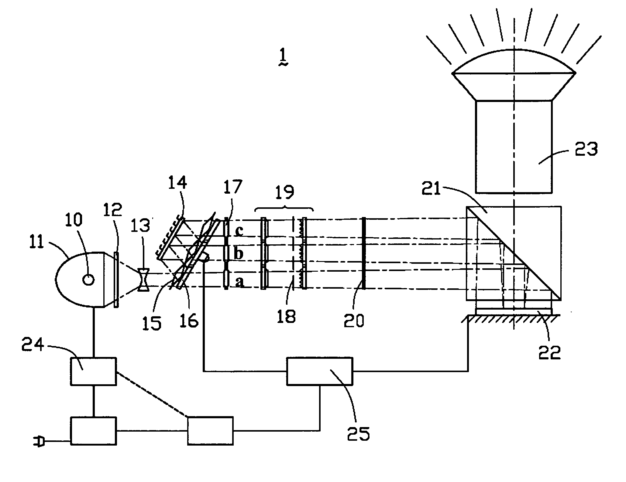
[0027] Referring to FIG. 4A, a projection display device 1 in accordance with a first embodiment of the present invention employs a reflective display panel that is preferably an LCoS panel 22. The projection display device 1 comprises an illumination portion, a light separating portion, a polarization conversion portion, an image display portion, and a control portion. The illumination portion is adapted to provide an illumination light beam, and includes a light source 10, a reflecting member 11, an optical filter 12, and a collimating lens 13. The light separating portion is adapted to sequentially separate the illumination light beam into a plurality of color light beams with different wavelengths that are projected onto the LCoS panel 22 in different light paths. The light separating portion preferably includes a reflector 14, a hole grid 15, a rotating color wheel 16, a relay lens 17, a line grid 18, and two integrators 19 each comprised of a lens array. The polarization conve...


PUM


Abstract

An objection display device (1) includes an illumination portion for providing an illumination light beam, a light separating portion for separating the illumination light beam into a plurality of color light beams (RGB) for being projected onto a reflective display panel (22), and a projection lens (23). The light separating portion includes a rotating color wheel (16) and a reflector (14) disposed parallel with each other. The rotating color wheel is comprised of a plurality of color filters each selectively transmitting a desired color component and reflecting the other color components of the illumination light beam incident on the color wheel at a predetermined angle. The reflected color components are incident on the reflector and reflected back by the reflector to the rotating color wheel for recycling at a given moment. The color components transmitted by corresponding color filters sequentially exit the color wheel via different light paths as color light beams with different wavelengths.

Description

BACKGROUND OF THE INVENTION [0001] 1. Field of the Invention [0002] The present invention relates to a projection display device, and particularly relates to a reflective projection display device with enhanced light utilization efficiency. [0003] 2. Description of Prior Art [0004] Currently, rear-projection display technologies mainly include LCD (Liquid Crystal Display), DLP (Digital Light Processing) and LCoS (Liquid Crystal on Silicon). Compared with LCD and DLP technologies, LCoS technology has the advantages of high resolution, high brightness, and simple structure, and also has the potential to yield very low-cost light engines. [0005] LCoS is also referred to as “reflective LCD”, where visible light is focused and reflected on the same side. An LCoS light engine system may be classified into a single-panel architecture and a three-panel architecture. The three-panel architecture splits light into three spatially separate primary color light beams, namely red, green, and blue...

Claims


Application Information

Patent Timeline
Patent Type & Authority Applications(United States)
IPC IPC(8): G03B21/14
CPCG03B21/14G03B21/2066G03B21/208G03B33/08
Inventor LIN, CHIN-HSIANG
Owner ASIA OPTICAL CO INC
Why Eureka
Try Eureka