Linear motor including extended tooth tips
a linear motor and tooth tip technology, applied in the direction of dynamo-electric machines, magnetic circuit rotating parts, magnetic circuit shape/form/construction, etc., can solve the problems of uneven thrust and uneven thrust of the rotor, and achieve the effect of not increasing the equipment siz
- Summary
- Abstract
- Description
- Claims
- Application Information
AI Technical Summary
Benefits of technology
Problems solved by technology
Method used
Image

Examples
first embodiment
[0059
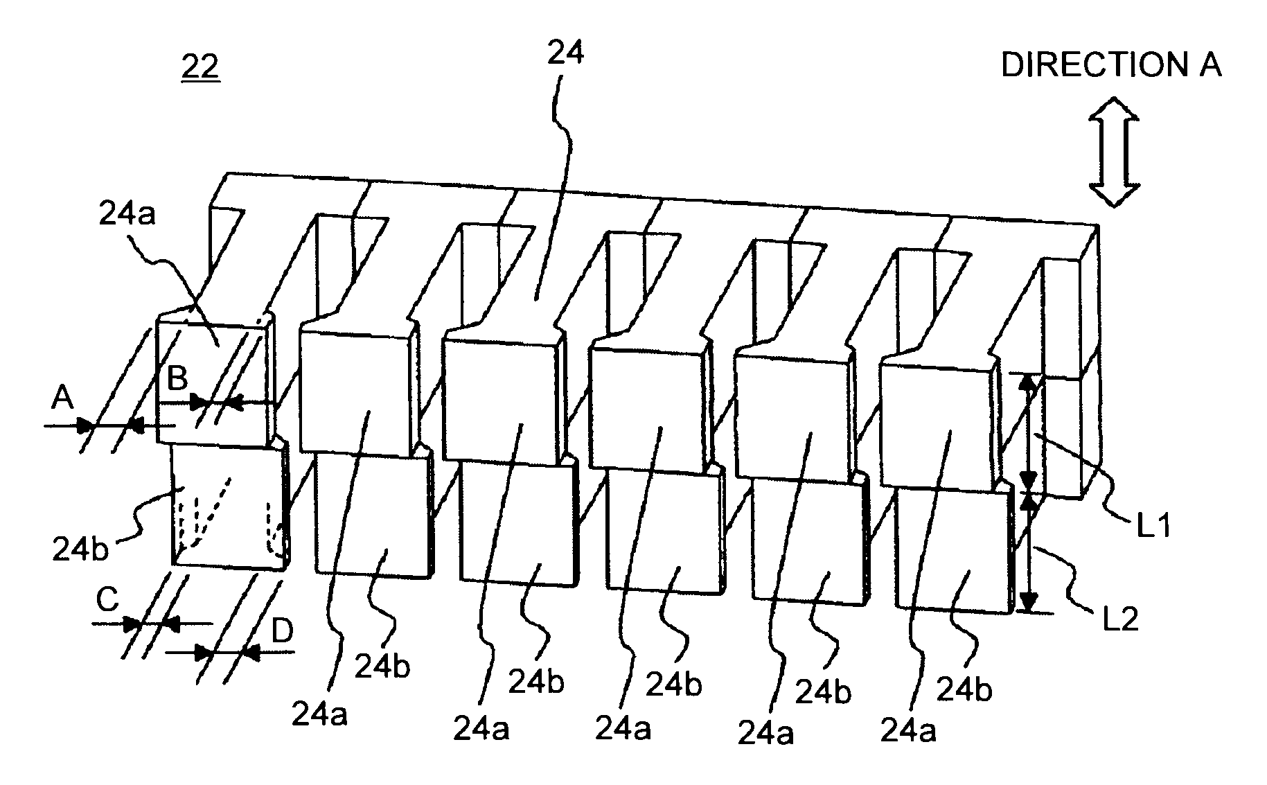
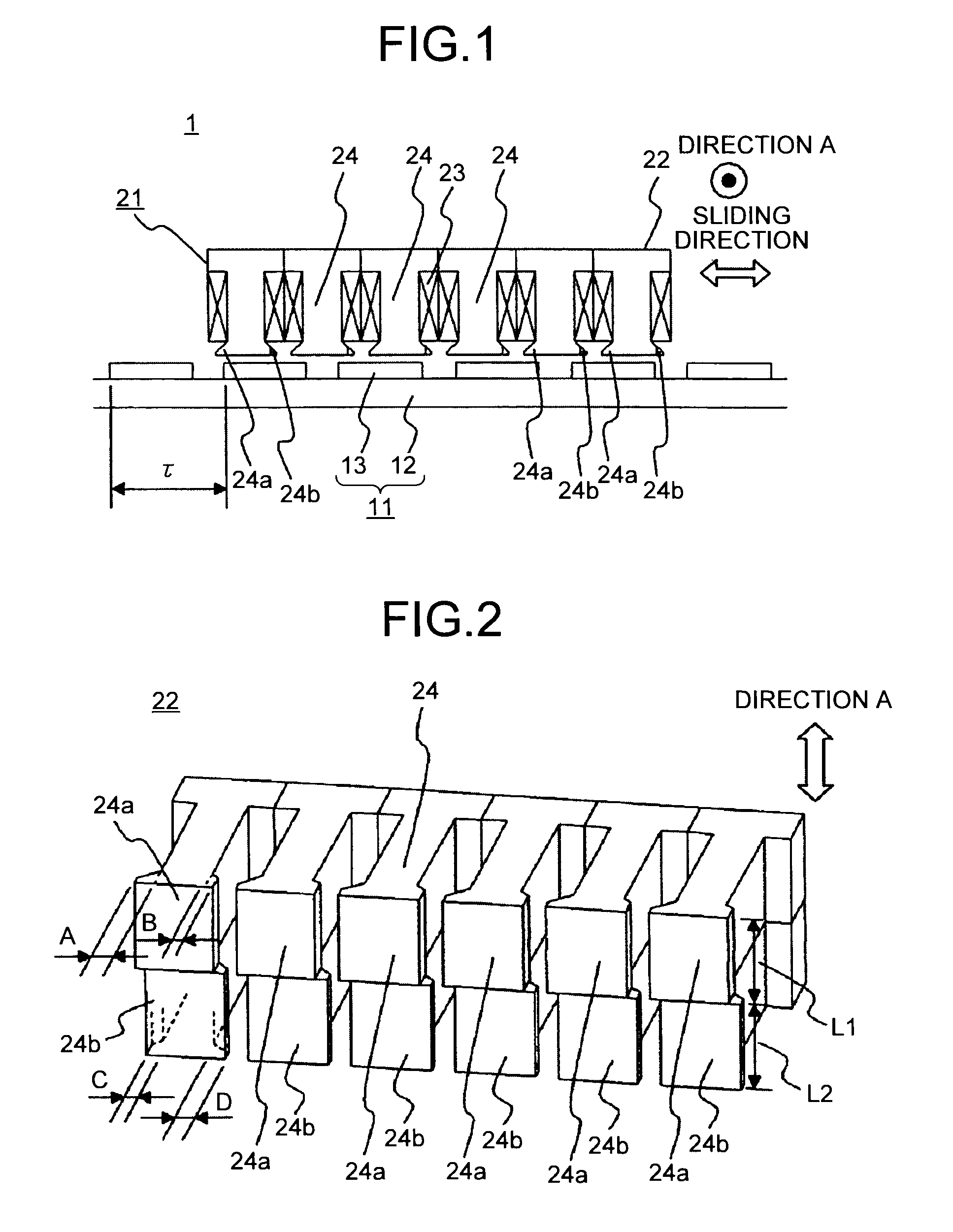
[0060]FIG. 1 is a sectional view of a linear motor according to a first embodiment of the present invention. In FIG. 1, a linear motor 1 includes a stator 11 and a rotor 21. This example according to the embodiment has a four-pole, six-toothed structure; however, the numbers of poles and teeth may be in any combination. The stator 11 and the rotor 21 are held with respect to each other with a predetermined gap therebetween, so that the stator 11 and the rotor 21 can be slid freely with respect to each other. A sliding direction is defined herein as a sliding direction in which the rotor 21 slides with respect to the stator 11. The stator 11 includes a field core 12 and a plurality of permanent magnets 13 to produce field poles. The permanent magnets 13 are arranged linearly on the field core 12 so that adjacent field poles oppose each other along the sliding direction. The permanent magnets 13 are arranged with a pole pitch τ. The rotor 21 includes an armature core 22 having a ...
second embodiment
[0072
[0073]FIG. 8 is a sectional view of a linear motor according to a second embodiment of the present invention. A linear motor 30 according to the second embodiment is different from the one according to the first embodiment in that no stepwise skew is provided to the outer side of the heads of two teeth located at both ends of the armature core in the sliding direction. In FIG. 8, structures with the same reference numerals as in FIG. 1 are the same as or equivalent to those shown in FIG. 1, and the same can be said throughout the entire description. The implementations of the structures described herein are given only by way of examples, and the present invention is not limited by such descriptions in any way.
[0074]FIG. 9 is a perspective view of an armature core 32 shown in FIG. 1. The armature core 32 includes teeth 24, 35, and 36. Extending portions that are extended in the sliding direction of a rotor 31 are formed at each of the head of the teeth 24, 35, and 36. The head o...
third embodiment
[0078
[0079]FIG. 12 is a sectional view of a linear motor according to a third embodiment of the present invention. A linear motor 40 according to the present embodiment is different from the one according to the first embodiment in that the stepwise skew is provided only to the inner side of the heads of two teeth located at both ends in the sliding direction. In FIG. 12, an armature core 42 includes teeth 44, 45, and 46. Extending portions that are extended in the sliding direction of a rotor 41 are formed at each of the head of the teeth 44, 45, and 46. The head of each of the teeth 45 and 46, located both ends in the sliding direction, is divided into two core blocks that form a plurality of areas along the direction A (stacking direction) that is perpendicular to the sliding direction of the rotor 41 and in parallel with the pole face of the permanent magnets 13. Ones of the core blocks are referred to as first core blocks 45a and 46a, and the others are referred to as second co...
PUM
 Abstract
Description
Claims
Application Information
 - R&D Engineer
- R&D Manager
- IP Professional
- Industry Leading Data Capabilities
- Powerful AI technology
- Patent DNA Extraction
Browse by: Latest US Patents, China's latest patents, Technical Efficacy Thesaurus, Application Domain, Technology Topic.
© 2024 PatSnap. All rights reserved.Legal|Privacy policy|Modern Slavery Act Transparency Statement|Sitemap