Linear motor

Active Publication Date: 2010-08-12
MITSUBISHI ELECTRIC CORP
View PDF11 Cites 20 Cited by
  • Summary
  • Abstract
  • Description
  • Claims
  • Application Information

AI Technical Summary

Benefits of technology

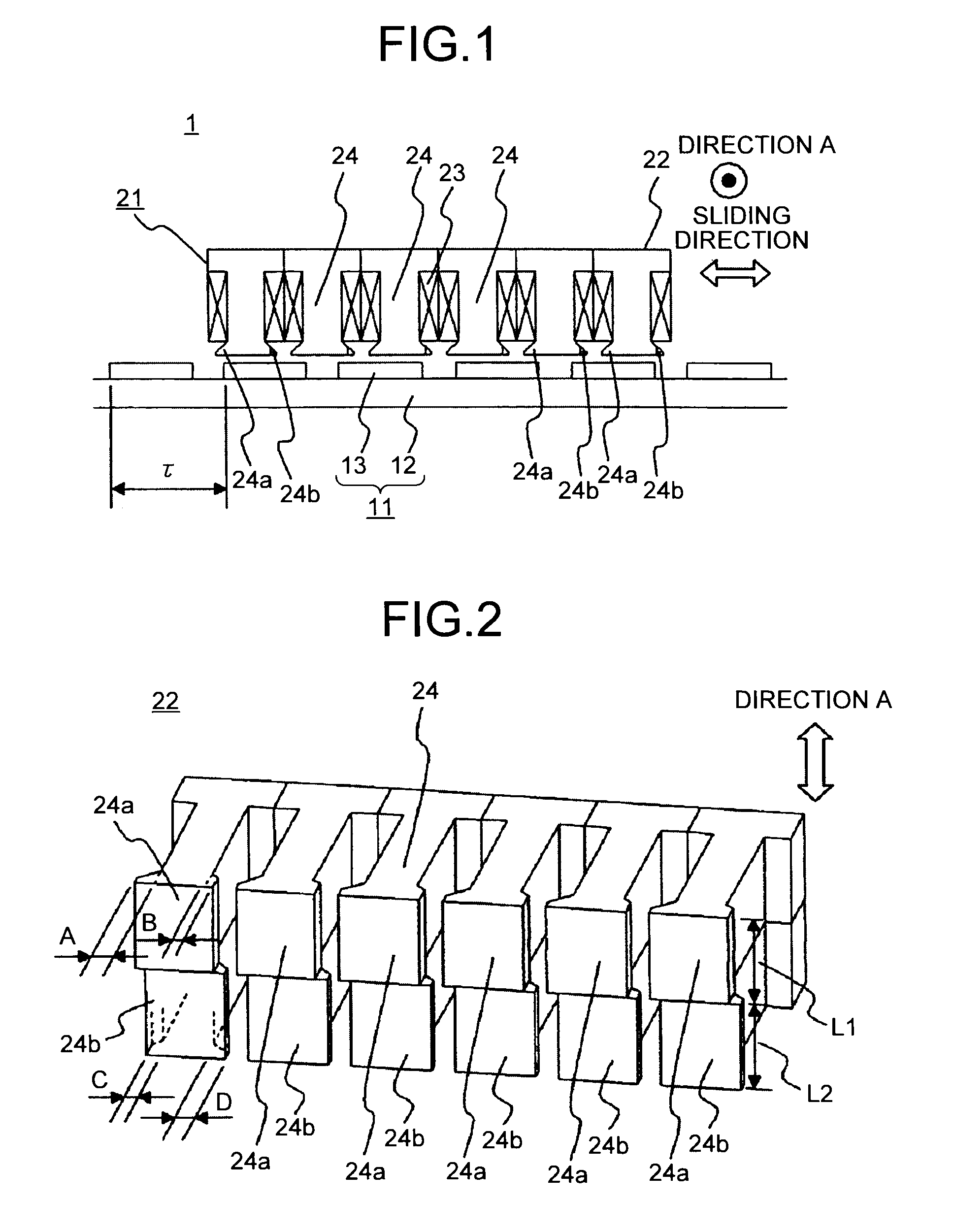
[0013]In the linear motor according to the present invention, at least the head of each of the teeth located at both ends of the armature core in the sliding direction is divided into a plurality of areas along the stacking direction, and at least one of the extended portions arranged on the adjacent areas is extended by a different length along the sliding direction. Therefore, the slot cogging thrust and the cogging thrust caused by the end effect of the rotor can be reduced simultaneously, without increasing the equipment size.

Problems solved by technology

The second-order cogging thrust further generates a fourth- and a sixth-order cogging thrusts that are doubles of a harmonic wave thereof, resulting in an uneven thrust due to the rotor.
This also results in an uneven thrust.

Method used


Image

  • Linear motor
  • Linear motor
  • Linear motor

Examples


first embodiment

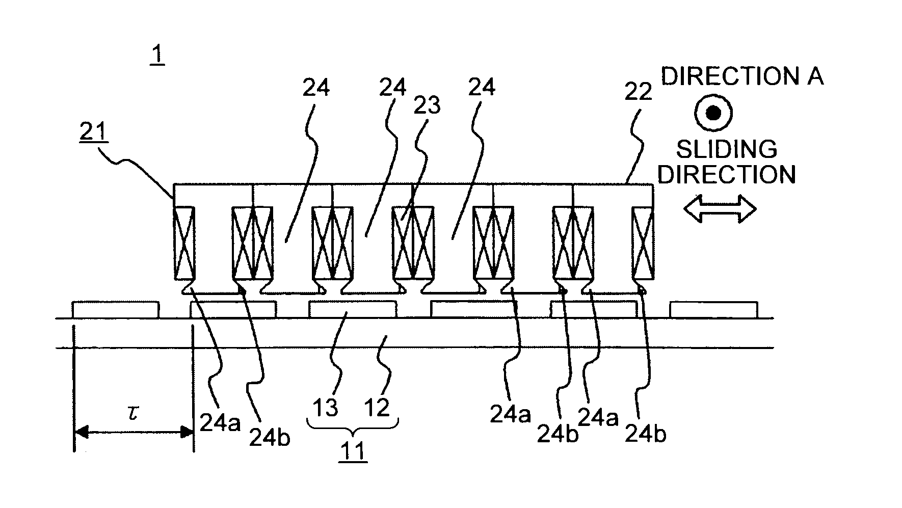
[0059]FIG. 1 is a sectional view of a linear motor according to a first embodiment of the present invention. In FIG. 1, a linear motor 1 includes a stator 11 and a rotor 21. This example according to the embodiment has a four-pole, six-toothed structure; however, the numbers of poles and teeth may be in any combination. The stator 11 and the rotor 21 are held with respect to each other with a predetermined gap therebetween, so that the stator 11 and the rotor 21 can be slid freely with respect to each other. A sliding direction is defined herein as a sliding direction in which the rotor 21 slides with respect to the stator 11. The stator 11 includes a field core 12 and a plurality of permanent magnets 13 to produce field poles. The permanent magnets 13 are arranged linearly on the field core 12 so that adjacent field poles oppose each other along the sliding direction. The permanent magnets 13 are arranged with a pole pitch T. The rotor 21 includes an armature core 22 having a plura...

second embodiment

[0071]FIG. 8 is a sectional view of a linear motor according to a second embodiment of the present invention. A linear motor 30 according to the second embodiment is different from the one according to the first embodiment in that no stepwise skew is provided to the outer side of the heads of two teeth located at both ends of the armature core in the sliding direction. In FIG. 8, structures with the same reference numerals as in FIG. 1 are the same as or equivalent to those shown in FIG. 1, and the same can be said throughout the entire description. The implementations of the structures described herein are given only by way of examples, and the present invention is not limited by such descriptions in any way.

[0072]FIG. 9 is a perspective view of an armature core 32 shown in FIG. 1. The armature core 32 includes teeth 24, 35, and 36. Extending portions that are extended in the sliding direction of a rotor 31 are formed at each of the head of the teeth 24, 35, and 36. The head of eac...

third embodiment

[0076]FIG. 12 is a sectional view of a linear motor according to a third embodiment of the present invention. A linear motor 40 according to the present embodiment is different from the one according to the first embodiment in that the stepwise skew is provided only to the inner side of the heads of two teeth located at both ends in the sliding direction. In FIG. 12, an armature core 42 includes teeth 44, 45, and 46. Extending portions that are extended in the sliding direction of a rotor 41 are formed at each of the head of the teeth 44, 45, and 46. The head of each of the teeth 45 and 46, located both ends in the sliding direction, is divided into two core blocks that form a plurality of areas along the direction A (stacking direction) that is perpendicular to the sliding direction of the rotor 41 and in parallel with the pole face of the permanent magnets 13. Ones of the core blocks are referred to as first core blocks 45a and 46a, and the others are referred to as second core bl...


PUM


Abstract

A linear motor includes a stator having field poles arranged linearly with opposing polarities arranged in an alternating manner; and a rotor having an armature core with teeth that faces a pole face of the field poles with a gap, and coils wound around the teeth. The stator and the rotor are supported in a slidable manner, a direction perpendicular to a sliding direction of the rotor and in parallel with the pole face is defined as a stacking direction. A head of each of the teeth has an extended portion extended in the sliding direction. At least heads of the teeth arranged at both ends of the armature core along the sliding direction is divided into a plurality of areas along the stacking direction. At least one of extended portions arranged on adjacent areas is extended by a different length along the sliding direction.

Description

TECHNICAL FIELD[0001]The present invention relates to a cogging reduction of a linear motor used for table feeding in an industrial machine such as a machine tool or semiconductor manufacturing equipment.BACKGROUND ART[0002]In a linear motor used for table feeding in an actuator of a machine tool or transporting equipment, if an armature coil of a rotor is shorter in length than an array of permanent magnets (an array of field magnets), because a magnetic circuit of the armature core is not endless, an end effect occurs. Thus, a one-cycle cogging thrust, that is a second-order cogging thrust, is generated in a pitch between the poles of the permanent magnet array. The second-order cogging thrust further generates a fourth- and a sixth-order cogging thrusts that are doubles of a harmonic wave thereof, resulting in an uneven thrust due to the rotor. Furthermore, because a first iron core has a slot in the same manner as in a conventional rotating motor, a slot cogging thrust is also p...

Claims


Application Information

Patent Timeline
IPC IPC(8): H02K41/03
CPCH02K29/03H02K41/03
Inventor NAKAYAMA, MISAYAMAGUCHI, SHINICHINAKA, KOKIITO, KAZUMASATANAKA, TOSHINORI
Owner MITSUBISHI ELECTRIC CORP
Why Eureka
Try Eureka