Turbomachine rotor disk

a technology of rotor disk and turbomachine, which is applied in the direction of liquid fuel engines, vessel construction, marine propulsion, etc., can solve the problems of air leakage toward the disk, reduced overall efficiency of the turbomachine, and large clearance at the axial ends of the platform, so as to achieve simple, economical and effective

Active Publication Date: 2012-10-02
SN DETUDE & DE CONSTR DE MOTEURS DAVIATION S N E C M A
View PDF14 Cites 12 Cited by
  • Summary
  • Abstract
  • Description
  • Claims
  • Application Information

AI Technical Summary

Benefits of technology

[0006]It is a particular objective of the invention to provide a simple, economical and effective solution to these various problems.
[0009]According to the invention, the liners perform an additional function by radially retaining the intern-blade platforms in position on the ribs of the rotor disk using locking means. The invention therefore makes it possible to reduce the clearance between the blade and the platform because the platform no longer needs to be inserted axially, locking being afforded by the liners. The lateral edges of the platform can thus perfectly correspond to the curvature of the blade airfoil section.
[0012]This system of locking using a translational movement of the protective liner allows the platform to be mounted on a rib of the disk with a minimum of clearance.
[0015]In certain turbomachine configurations, the rotor blade roots are mounted in cavities of the disk that make an angle with the axis of the disk. Thus, when the blades are mounted in the cavities of the disk, there are unequal thicknesses of rib radially retaining the blades on each side of the blade root and this can give rise to premature blade root wear. The use of helicoidal profiles for the cavities and ribs of the disk makes it possible to keep constant thicknesses on each side of the blade roots over the entire length of the disk, the liners having a helicoidal profile so that they can be fitted onto the ribs.

Problems solved by technology

However, because of the fitting and removal dynamics, there needs to be some clearance between the edges of the platforms and the airfoil sections and this gives rise to air leaks toward the disk.
This clearance is particularly large at the axial ends of the platform.
Thus, the buildup of blade / platform clearances over the entire disk leads to a reduction in the overall efficiency of the turbomachine.
However, techniques such as this entail the incorporation of additional components, making the turbomachines heavier.

Method used


Image

  • Turbomachine rotor disk
  • Turbomachine rotor disk
  • Turbomachine rotor disk

Examples


Embodiment Construction

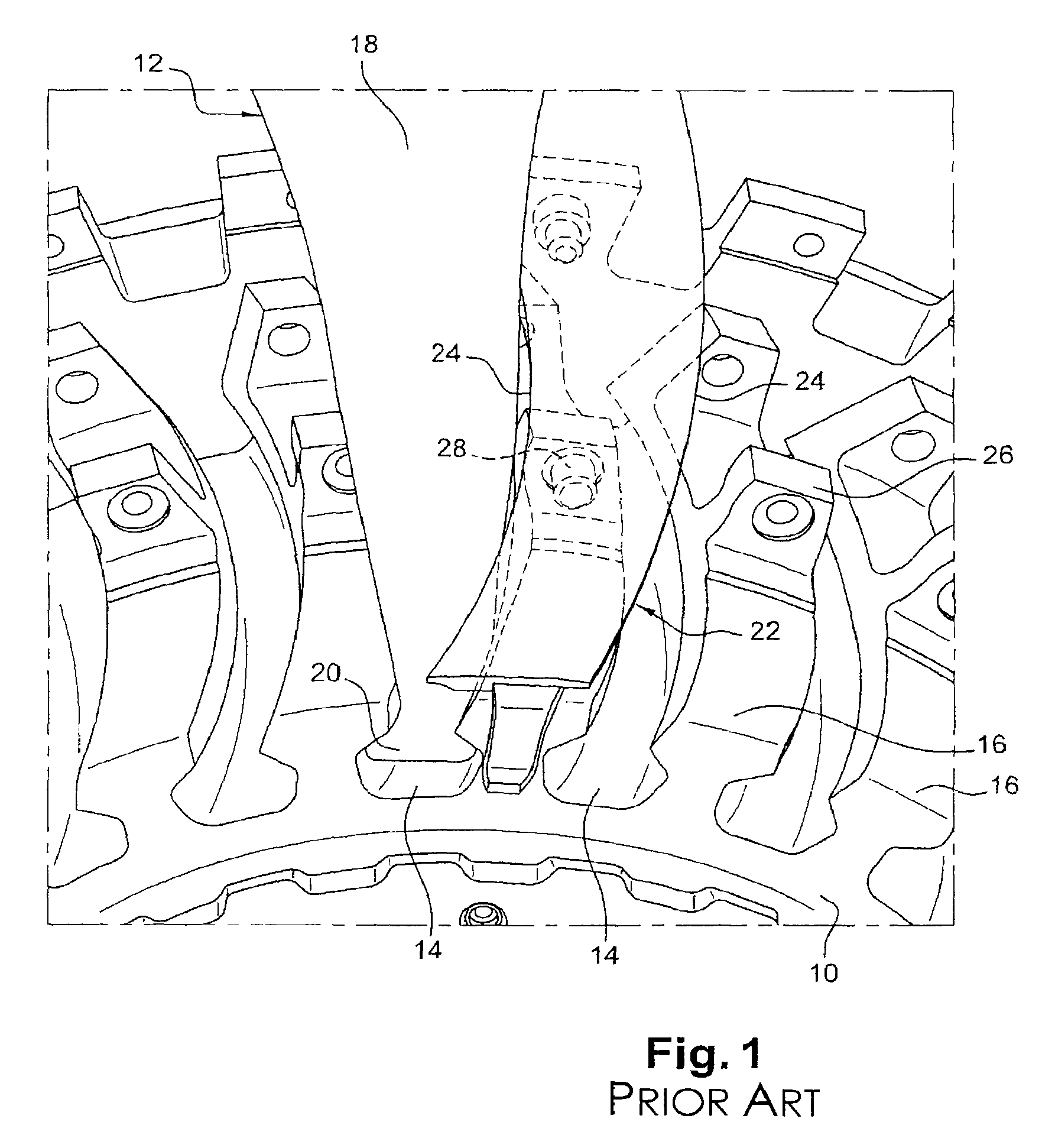
[0024]Reference is made first of all to FIG. 1 which depicts part of a turbomachine disk 10 bearing a blade 12 according to the prior art. The disk 10 at its periphery comprises an alternation of cavities 14 and of ribs 16 extending longitudinally over the entire length of the disk 10. The rotor blade 12 formed of an airfoil section 18 connected to a blade root 20 is engaged and retained radially in a cavity 14 of the disk 10. A platform 22 is positioned on a rib 16 of the disk 10, the edges 24 of the platform 22 being positioned close enough to the airfoil section 18 of the contiguous blade 12 that flows of air toward the disk 10 are prevented. The platform 22 is fixed by inwardly-extending radial flanges onto outwardly extending radial flanges 26 of a rib 16 of the disk 10. Rods 28 inserted in the flanges 26 of the disk 10 and the flanges of the platform 22 radially retain the platform 22 on the rib 16. The dynamics of fitting and removing the platform 22 dictate that the flanges ...


PUM


Abstract

A turbomachine rotor disk including inter-blade platforms fixed to ribs delimited by cavities in which blade roots are retained, and protective liners mounted between the flanks of the cavities of the disk and the blade roots is disclosed. The protective liners have a C-shaped cross section so that they can be fitted translationally and retained radially on the ribs of the disk and constitute a locking device which locks the platforms on the ribs of the disk.

Description

BACKGROUND OF THE INVENTION AND DESCRIPTION OF THE PRIOR ART[0001]The present invention relates to a fan rotor disk of a turbomachine such as an airplane turbojet engine.[0002]In the known art, a rotor disk is formed at its periphery with an alternation of cavities and of ribs and bears a plurality of blades each formed of an airfoil section connected to a root engaged axially and retained radially in a cavity belonging to the disk. Platforms are fixed between the blades by radial flanges connected to corresponding radial flanges formed on the ribs of the disk.[0003]The dynamics involved in mounting and removing the platforms onto and off the ribs of the disk entails that the platform perform a translational movement along the rib so that orifices in the flanges of the platform engage with pegs or rods provided on the flanges of the disk.[0004]In a turbomachine, the lateral edges of the platforms have to be close enough to the blade airfoil sections to prevent parasitic flow of air ...

Claims


Application Information

Patent Timeline
Patent Type & Authority Patents(United States)
IPC IPC(8): F01D5/30
CPCF01D5/3007F01D5/3092F01D5/323F04D29/322F04D29/644
Inventor BELMONTE, OLIVIER
Owner SN DETUDE & DE CONSTR DE MOTEURS DAVIATION S N E C M A
Why Eureka
Try Eureka