Aircraft propelling assembly including a duct forming a thermal barrier integrated in the caisson of the rigid structure of the engine mounting system

a technology of thermal barrier and propelling assembly, which is applied in the direction of power plant construction, aircraft power plants, lighting and heating apparatus, etc., can solve the problems of increasing mass and achieve the effect of simple, economical and effectiv

Active Publication Date: 2018-05-22
AIRBUS OPERATIONS (SAS)
View PDF16 Cites 0 Cited by
  • Summary
  • Abstract
  • Description
  • Claims
  • Application Information

AI Technical Summary

Benefits of technology

[0015]The invention aims, in particular, to provide a simple, economical and effective solution to these problems, making it possible to at least partially avoid the abovementioned drawbacks.
[0019]a thermal protection system comprising a conduit forming a thermal barrier to protect the box from the heat of the engine.
[0021]Thus, the internal volume of the box is used to house the conduit of the thermal protection system, such that the latter no longer requires specific volume to be taken into account when designing the propulsion assembly.

Problems solved by technology

However, the arrangement of this conduit beneath the box results in the need to assign a specific volume to the conduit when designing and dimensioning the propulsion assembly.
Moreover, such an arrangement of the conduit results in an increase in mass, which is not desirable.

Method used


Image

  • Aircraft propelling assembly including a duct forming a thermal barrier integrated in the caisson of the rigid structure of the engine mounting system
  • Aircraft propelling assembly including a duct forming a thermal barrier integrated in the caisson of the rigid structure of the engine mounting system
  • Aircraft propelling assembly including a duct forming a thermal barrier integrated in the caisson of the rigid structure of the engine mounting system

Examples


Embodiment Construction

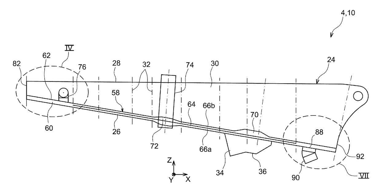
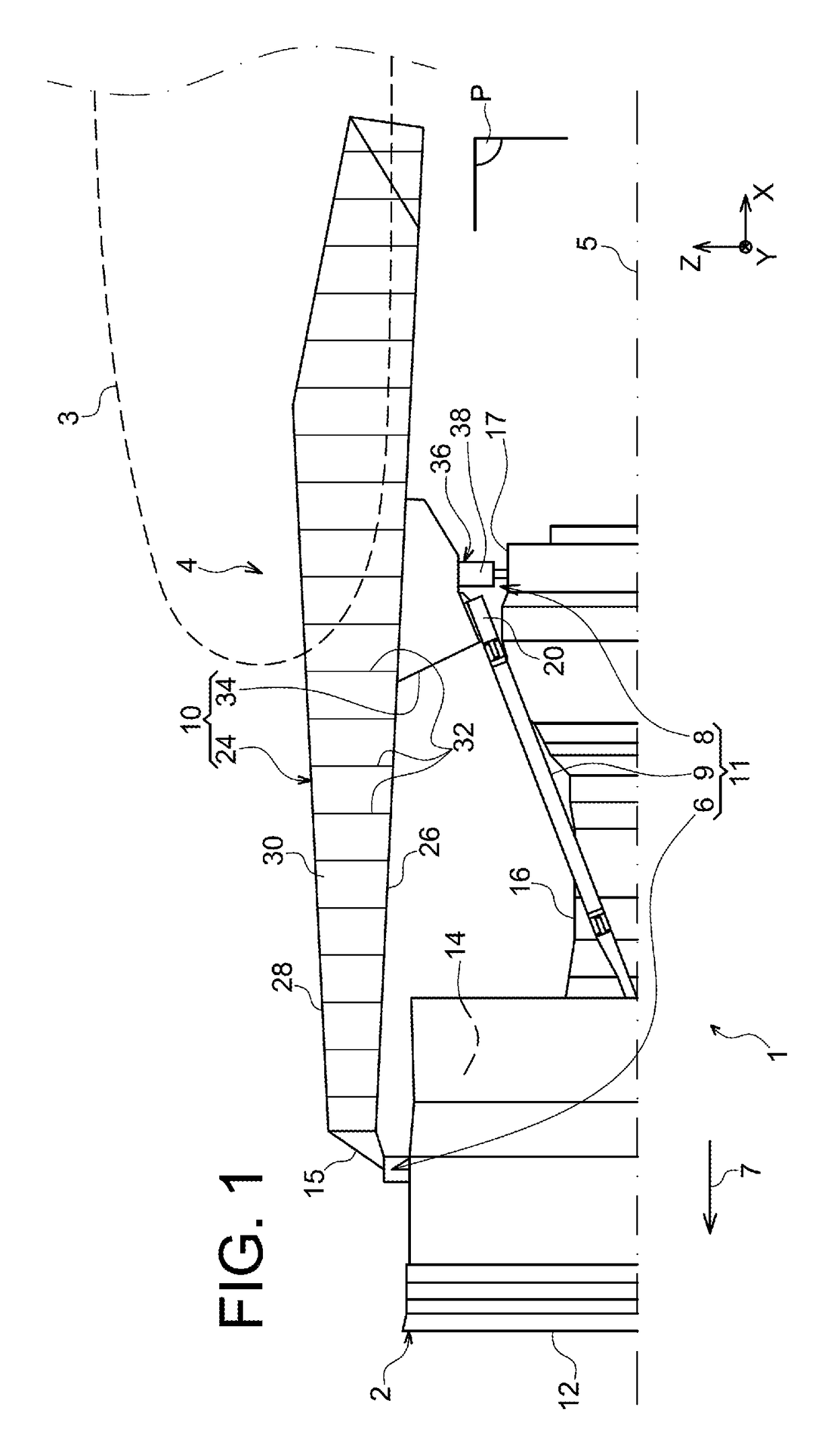
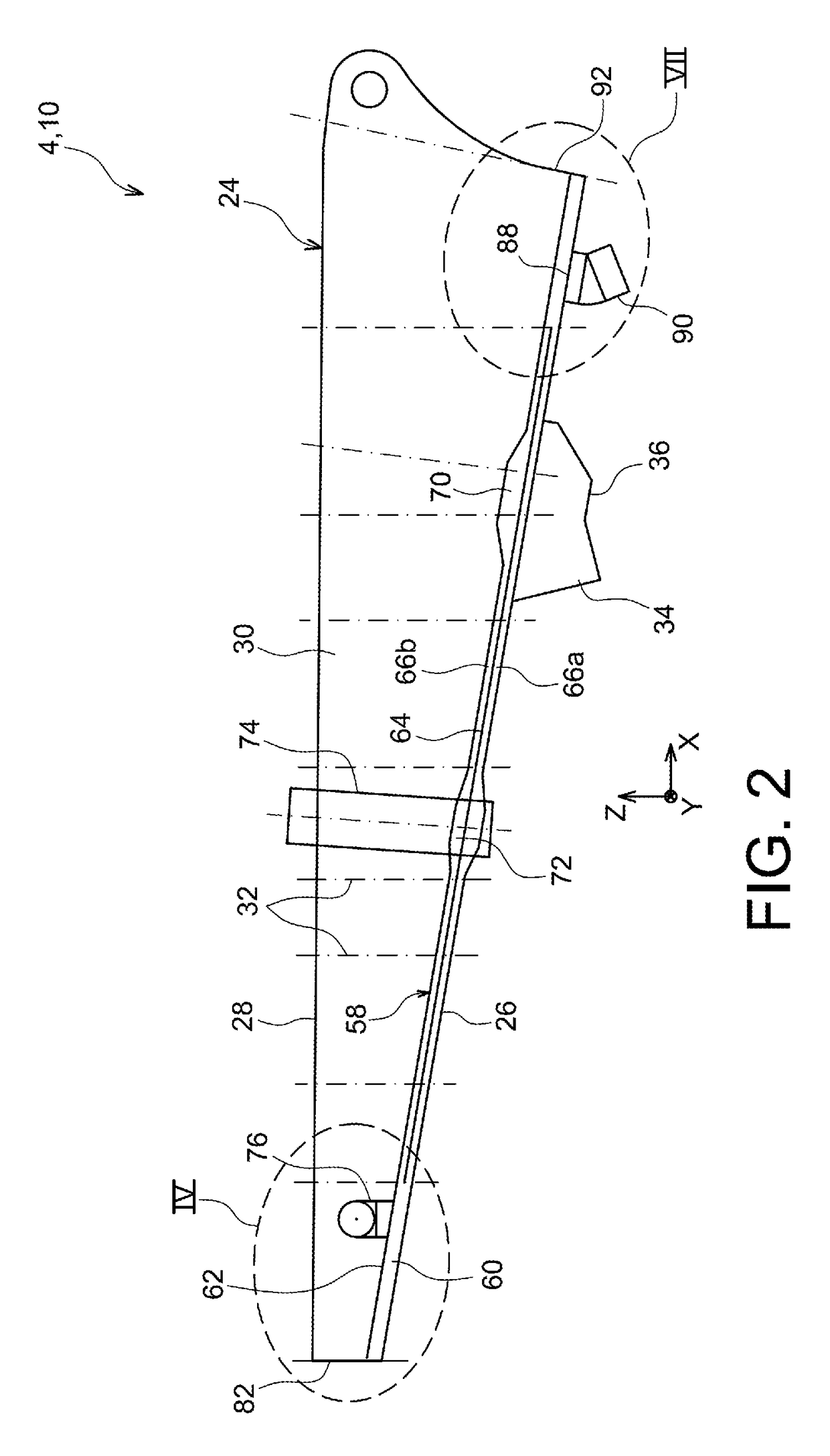
[0053]FIG. 1 illustrates an aircraft, more particularly a propulsion assembly 1 fixed beneath a wing 3 of this aircraft. Overall, the propulsion assembly 1 comprises an engine 2 such as a jet engine and an attachment pylon 4, the latter comprising in particular a rigid structure 10 and a mounting system 11 comprising a plurality of engine attachments 6, 8 and a device for taking up thrust forces 9. The mounting system 11 is interposed between the engine 2 and the rigid structure 10. By way of indication, the propulsion assembly 1 is designed to be surrounded by a nacelle (not shown in this figure), and the attachment pylon 4 comprises another set of attachments (not shown) by means of which it is possible to hang the propulsion assembly 1 beneath the wing 3 of the aircraft.

[0054]In the following description, the X direction is the longitudinal direction of the attachment pylon 4, which can also be considered to coincide with the longitudinal direction of the jet engine 2, this X dir...


PUM


Abstract

Housing a conduit of a thermal protection system of a rigid structure of an attachment pylon in an aircraft propulsion assembly within a box of the rigid structure, so as to take advantage of the volume within the rigid structure. The elements forming the conduits thus form an integral part of the rigid structure and can thus play a structural role.

Description

CROSS-REFERENCES TO RELATED APPLICATIONS[0001]This application claims the benefit of French patent application No. 1454183 filed on May 9, 2014, the entire disclosures of which are incorporated herein by way of reference.BACKGROUND OF THE INVENTION[0002]The present invention relates to the field of engine attachment pylons designed to be interposed between an aircraft wing and an engine, and more particularly to a propulsion assembly comprising such an attachment pylon.[0003]The invention can be used on any type of aircraft equipped for example with jet engines or turboprops.[0004]This type of attachment pylon, also called “EMS” (Engine Mounting Structure), makes it possible, for example, to hang an aircraft engine beneath the wing of the aircraft, or to mount such an engine above the wing.[0005]In general, such an attachment pylon is provided in order to constitute the connection interface between an aircraft engine and the wing of the aircraft. It allows the forces generated by th...

Claims


Application Information

Patent Timeline
Patent Type & Authority Patents(United States)
IPC IPC(8): B64D27/26F28F3/02
CPCB64D27/26F28F3/02B64D2027/266B64D2027/264
Inventor BROCHARD, WOLFGANGHERNANDEZ-PEREZ, MISAELBELLOC, YVES
Owner AIRBUS OPERATIONS (SAS)
Why Eureka
Try Eureka