Turbine engine comprising means for axially homogenising the temperature of an inner ring of a roller bearing

a technology of axial homogenisation and turbine engine, which is applied in the direction of bearing cooling, machines/engines, mechanical equipment, etc., can solve problems such as axial dissymmetry, and achieve the effect of simple, economical and effectiv

Active Publication Date: 2022-05-10
SN DETUDE & DE CONSTR DE MOTEURS DAVIATION S N E C M A
View PDF16 Cites 0 Cited by
  • Summary
  • Abstract
  • Description
  • Claims
  • Application Information

AI Technical Summary

Benefits of technology

[0008]The invention in particular has for purpose to provide a simple, economical and effective solution to this problem.
[0013]The invention thus makes it possible to improve the thermal homogeneity, in the axial direction, of the inner ring.
[0014]This results in a possibility of reducing the dimensioning of the internal clearances of the roller bearing, in comparison with the roller bearings of turbine engines of a known type.

Problems solved by technology

This can result in an axial dissymmetry of the exposure to heat of such a bearing, in particular of the inner ring of the bearing, with such a dissymmetry having for consequence the existence of an axial thermal gradient within the inner ring.

Method used


Image

  • Turbine engine comprising means for axially homogenising the temperature of an inner ring of a roller bearing
  • Turbine engine comprising means for axially homogenising the temperature of an inner ring of a roller bearing
  • Turbine engine comprising means for axially homogenising the temperature of an inner ring of a roller bearing

Examples


Embodiment Construction

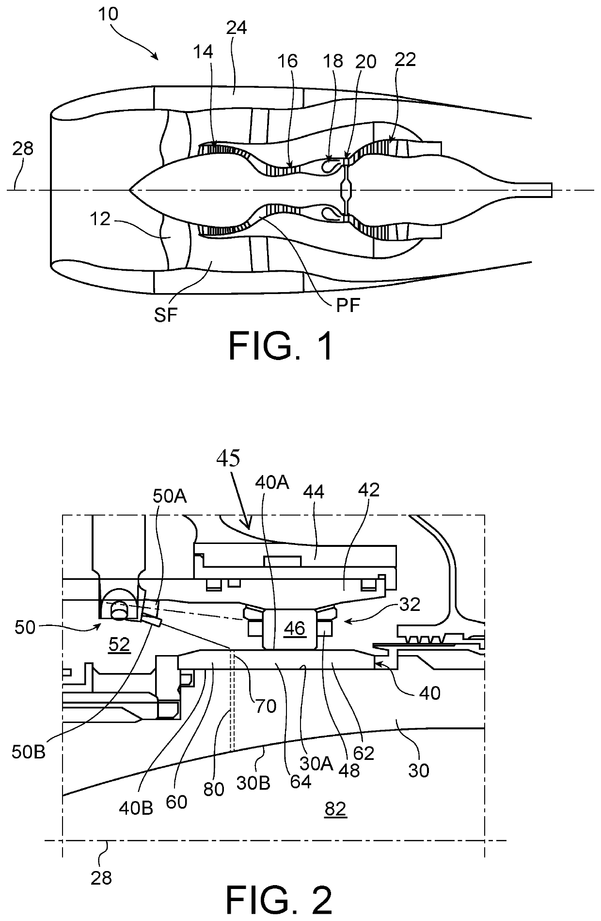
[0037]FIG. 1 shows a turbine engine 10 for an aircraft, generally comprising a fan 12 configured for the aspiration of a flow of air being divided downstream from the fan into a primary flow circulating in a primary flow channel, hereinafter referred to as primary duct PF, within a core of the turbine engine, and a secondary flow bypassing this core in a secondary flow channel, hereinafter referred to as secondary duct SF.

[0038]The turbine engine is for example of the bypass and two-spool type. The core of the turbine engine thus comprises, generally, a low-pressure compressor 14, a high-pressure compressor 16, a combustion chamber 18, a high-pressure turbine 20 and a low-pressure turbine 22.

[0039]The respective rotors of the high-pressure compressor and of the high-pressure turbine are connected by a rotor shaft referred to as “high-pressure shaft”, while the respective rotors of the low-pressure compressor and of the low-pressure turbine are connected by a rotor shaft referred to ...


PUM


Abstract

A turbine engine comprises a rotor shaft and a roller bearing supporting the shaft in rotation along an axis. The bearing comprises an inner ring, an outer ring, and rolling elements engaged between the inner and outer rings. The inner ring has a first axial end annular portion that is more exposed to heat during operation than a second axial end annular portion thereof. The turbine engine further comprises an oil injection device configured to supply the rolling elements with oil for lubrication of the latter. In order to homogenise the temperature of the inner ring, the latter comprises through-holes formed in the first axial end annular portion and distributed around the axis in order to allow for a circulation of oil coming from the oil injection device through the first axial end annular portion, thereby providing additional cooling to the first end annular portion.

Description

[0001]This application claims priority from French Patent Application 1860015 filed Oct. 29, 2018, the entire content of which is incorporated by reference herein.TECHNICAL FIELD[0002]The present invention relates to the field of turbine engines, in particular for aircraft, and relates more particularly to the question of cooling a bearing in such a turbine engine.PRIOR ART[0003]The rotor shaft or shafts in turbine engines are supported and guided in rotation by bearings, which are in general roller bearings lubricated by means of a circulation of oil.[0004]The thermal environment of such a bearing within a turbine engine determines the thermal behaviour of the bearing, and in particular determines the internal clearances of the bearing that must be provided when dimensioning the bearing so as to allow for the thermal expansions of the various constituents thereof during operation.[0005]As these internal clearances have an influence on the overall dynamics of the turbine engine, it ...

Claims


Application Information

Patent Timeline
Patent Type & Authority Patents(United States)
IPC IPC(8): F01D25/16F01D25/18
CPCF01D25/16F01D25/18F05D2220/32F05D2240/54F01D25/162F16C19/06F16C19/26F16C19/525F16C33/667F16C33/6677F16C37/007F16C2360/23F05D2220/40F01D25/125F05D2240/50F05D2260/98
Inventor PIKOVSKY, CATHERINEGATTEAU, THOMAS GABRIEL ELIESIMONET, AUDE
Owner SN DETUDE & DE CONSTR DE MOTEURS DAVIATION S N E C M A
Why Eureka
Try Eureka