Supercharge Your Innovation With Domain-Expert AI Agents!

De-interlacing video

a technology of interlaced video and interpolation, which is applied in the direction of signal generators with optical-mechanical scanning, picture reproducers using projection devices, and television systems, etc., and can solve the problem that the use of interlaced scanning is becoming less attractiv

Inactive Publication Date: 2013-04-16
GRASS VALLEY LTD
View PDF10 Cites 0 Cited by
  • Summary
  • Abstract
  • Description
  • Claims
  • Application Information

AI Technical Summary

Benefits of technology

[0008]The inventors have appreciated that certain motion measurement techniques provide information additional to the motion vector values and that this additional information can be used to obtain superior de-interlacing of images.

Problems solved by technology

Now that more modern (often transform-based) data compression methods are available and electron-beam-scanned displays are less common, the use of interlaced scanning is becoming less attractive.

Method used


Image

  • De-interlacing video
  • De-interlacing video

Examples


Embodiment Construction

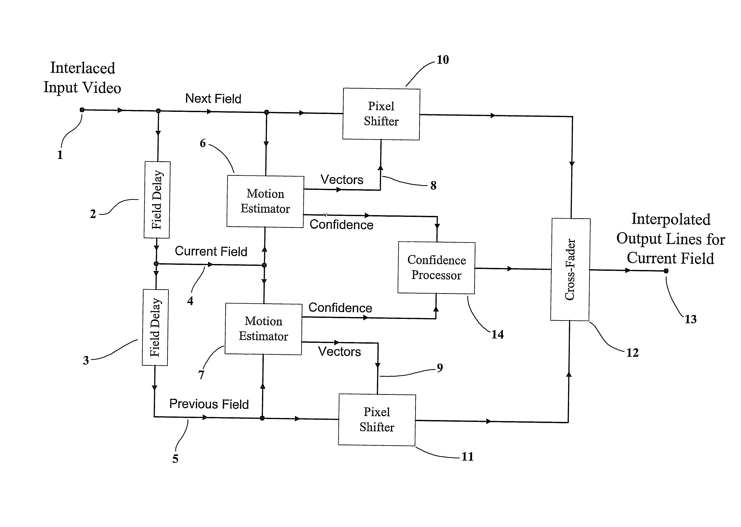
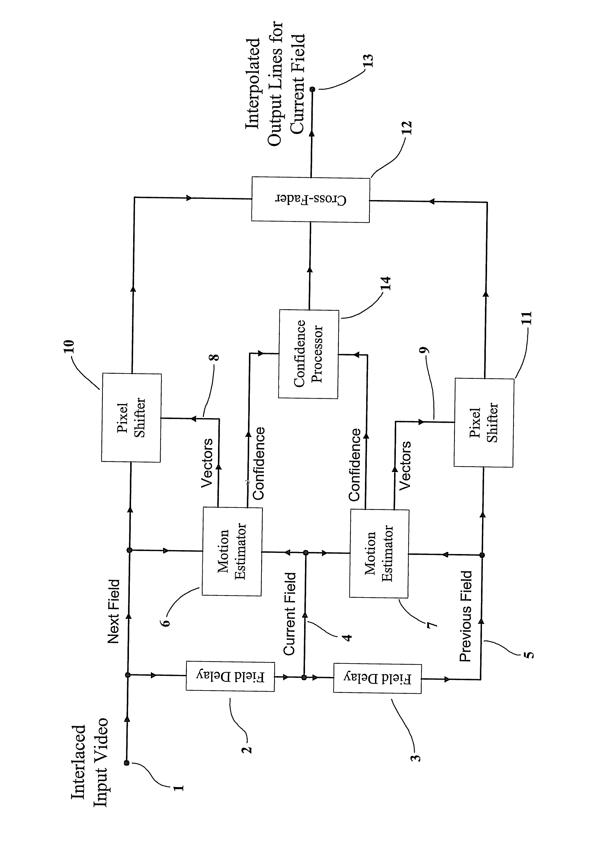
[0025]FIG. 1 shows an example of a de-interlacing system according to the invention. An input interlaced video signal (1) is required to be de-interlaced; i.e. for every input field an additional set of pixels is required located at vertical positions mid way between the existing pixels and representing the same point in time as the existing pixels.

[0026]The input sequence of interlaced fields (1) is delayed in two, cascaded field delays (2) (3). If the output (4) from the first field delay (2) is regarded as the “current field”, then the un-delayed input (1) can be considered the “next field”, and the output (5) from the second field delay (3) can be considered to be the “previous field”.

[0027]A motion estimator (6) compares the current field (4) with the next field (1) so as to obtain motion vectors (8). These vectors define, for each pixel of the current field (4), the equivalent position of the object portrayed by that pixel in the next field (1). These vectors (8) are therefore...


PUM


Abstract

A video de-interlacer forms a first new-pixel value from motion compensation of a pixel of a previous field with a first motion vector and forms a second new-pixel value from motion compensation of a pixel of a next field with a second motion vector. These two new-pixel values are then summed with a weighting which depends upon the respective confidence values associated with the two motion vectors.

Description

CROSS-REFERENCE TO RELATED APPLICATIONS[0001]This application claims priority from Great Britain Patent Application No. 0706988.3, filed Apr. 11, 2007, which is hereby incorporated by reference.FIELD OF INVENTION[0002]This invention concerns spatio-temporal interpolation of images.BACKGROUND OF THE INVENTION[0003]Two to one interlaced scanning, in which the spatial sampling grid is offset vertically by half the vertical sample pitch on alternate temporal samples, is a very common method of reducing the bandwidth of television images. Now that more modern (often transform-based) data compression methods are available and electron-beam-scanned displays are less common, the use of interlaced scanning is becoming less attractive.[0004]De-interlacing can form part of many video processes; by de-interlacing at the input to a process, that process can be made easier. Examples include standards conversion and re-scaling.[0005]It is therefore frequently necessary to convert an interlaced ima...

Claims


Application Information

Patent Timeline
Patent Type & Authority Patents(United States)
IPC IPC(8): H04N7/01H04N5/44
CPCH04N7/012H04N5/144H04N5/145
Inventor HUNS, THOMASELEY, DAN
Owner GRASS VALLEY LTD
Features
  • R&D
  • Intellectual Property
  • Life Sciences
  • Materials
  • Tech Scout
  • Unparalleled Data Quality
  • Higher Quality Content
  • 60% Fewer Hallucinations
Learn More