Position detecting device having opposite-phase magnetic-field generating coil, medical device guiding system, position detecting method, and medical device guiding method

a magnetic field generation coil and position detection technology, applied in the field of position detecting devices, can solve the problems of high sensitivity of detecting coils, loss of detection objects, and increased device size, so as to reduce the size and cost of devices

Inactive Publication Date: 2013-05-21
OLYMPUS CORP
View PDF8 Cites 12 Cited by
  • Summary
  • Abstract
  • Description
  • Claims
  • Application Information

AI Technical Summary

Benefits of technology

[0011]The present invention has been made in view of the situation described above, and it is an object thereof to provide a position detecting device and a medical device guiding system in which it is possible to dispose a magnetic-field detecting unit in proximity to a detected object, so that it is possible to precisely detect the position of the detected object, while reducing the size and cost of the device.
[0050]An advantage is provided in that it is possible to dispose a magnetic-field detecting unit in proximity to a detected object, so that the position of the detected object can be detected precisely, while reducing the size and cost of the device.

Problems solved by technology

In this case, if the direction of the opening of the built-in coil in the detected object perpendicularly intersects the first magnetic field, an induced magnetic field is not generated, thus causing the problem that the detected object is lost from detection.
Therefore, when applied to a detection space that accommodates the entirety of an object to be inspected, such as a subject, the size of the device conceivably increases.
In the case where the size of the device increases, the detection space becomes large and the magnetic-field detecting units become remote from the detected object, so that there is conceivably a disadvantage that detecting coils having a high sensitivity are needed or magnetic-field generating units capable of generating intense and large magnetic fields are needed.

Method used


Image

  • Position detecting device having opposite-phase magnetic-field generating coil, medical device guiding system, position detecting method, and medical device guiding method
  • Position detecting device having opposite-phase magnetic-field generating coil, medical device guiding system, position detecting method, and medical device guiding method
  • Position detecting device having opposite-phase magnetic-field generating coil, medical device guiding system, position detecting method, and medical device guiding method

Examples


first embodiment

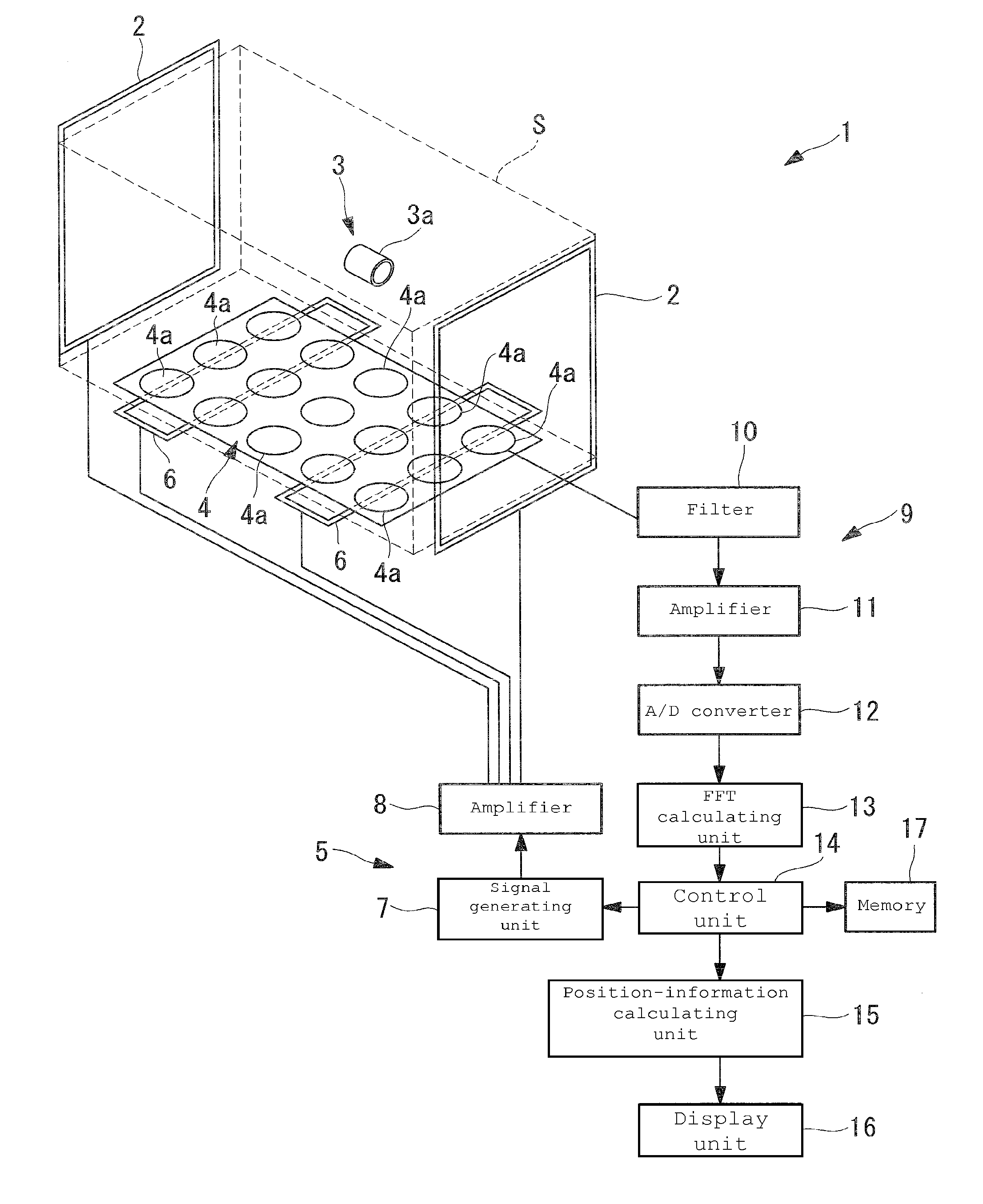
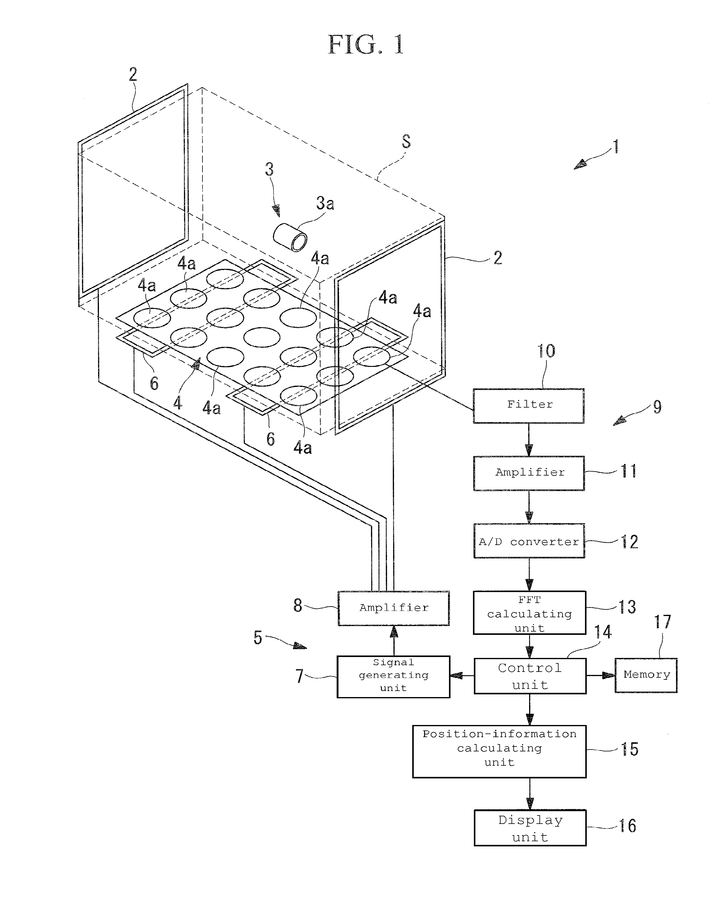
[0084]A position detecting device 1 according to the present invention will be described below with reference to FIGS. 1 to 5.

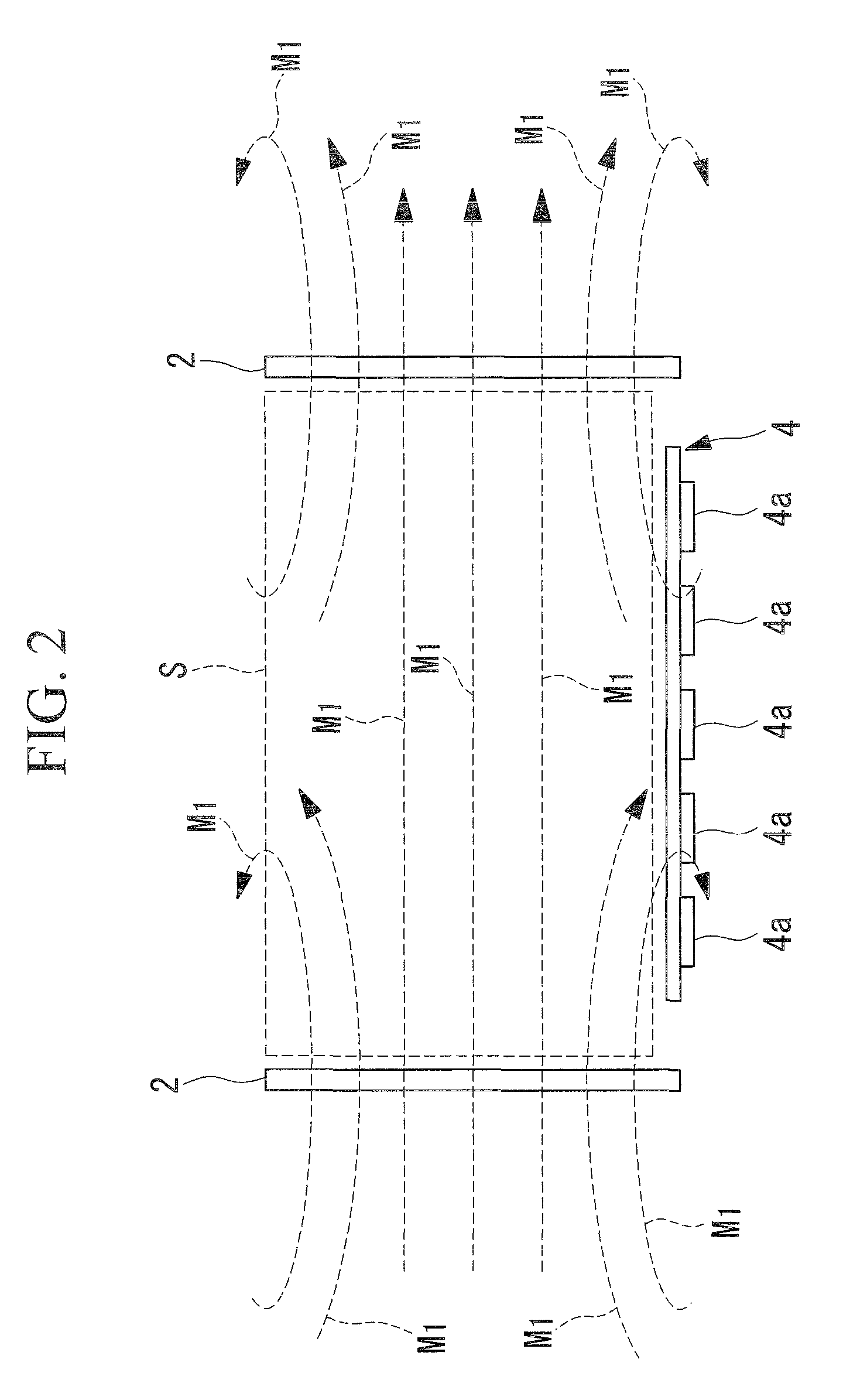
[0085]As shown in FIG. 1, the position detecting device 1 according to the first embodiment includes magnetic-field generating coils (first magnetic-field generating unit) 2 that generate an alternating magnetic field (hereinafter referred to as a first magnetic field M1) penetrating a detection space S in one direction, a magnetic-field sensor (magnetic-field detecting unit) 4 that detects an induced magnetic field generated by a built-in coil 3a installed in a detected object 3, a driving unit 5 that drives and controls the magnetic-field generating coils 2, a detecting unit (magnetic-field detecting unit) 9 that processes signals output from a magnetic-field sensor 12, and opposite-phase-magnetic-field generating coils (second magnetic-field generating unit) 6 that generate opposite-phase magnetic fields (second magnetic fields M2).

[0086]An example of the ...

second embodiment

[0125]Next, a position detecting device 30 according to the present invention will be described below with reference to FIGS. 11 to 15.

[0126]In the description of this embodiment, parts configured identically to those of the position detecting device 1 according to the first embodiment are designated by the same reference signs, and a description thereof will be omitted.

[0127]The position detecting device 30 according to this embodiment differs from the position detecting device 1 according to the first embodiment in that, as shown in FIG. 11, magnetic-field generating coils 6, 31a to 31c, and 33 are disposed along a cylindrical surface.

[0128]As shown in FIG. 11, the position detecting device 30 according to this embodiment includes magnetic-field generating coils 31a that are disposed at positions on either side of a detection space S in a radial direction, the detection space S having a center line in a substantially horizontal direction, and that generate a substantially horizont...


PUM


Abstract

Provided is a position detecting device including a first magnetic-field generating unit including at least one magnetic-field generating coil and that generates a first magnetic field in a detection space where a detected object provided with a circuit including at least one built-in coil is disposed; a magnetic-field detecting unit having a plurality of detecting coils arrayed to detect an induced magnetic field generated from the built-in coil by the generated first magnetic field; and a second magnetic-field generating unit including at least one magnetic-field generating coil, that generates a second magnetic field, and including a magnetic-field component having a phase substantially opposite to the first magnetic field and entering the detecting coils, wherein the first magnetic-field generating unit and the detecting coils are disposed so that a generating direction of the first magnetic field and a detecting direction of the induced magnetic field intersect each other.

Description

TECHNICAL FIELD[0001]The present invention relates to a position detecting device, a medical device guiding system, a position detecting method, and a medical device guiding method.BACKGROUND ART[0002]Recently, research and development are underway to enable practical use of capsule medical devices (detected objects), such as a swallowable capsule endoscope that is swallowed by a subject or the like and passed through a body cavity tract so that an image inside the body cavity tract at a target site can be acquired.[0003]In order to guide such a capsule medical device to a designated location inside a body cavity tract, it is necessary to precisely detect the position of the capsule medical device inside the body cavity tract.[0004]As a position detecting device for precisely detecting the position of a capsule medical device in a body cavity tract, a position detecting device is known in which a magnetic field is applied from the outside of a subject or the like and in which an ind...

Claims


Application Information

Patent Timeline
Patent Type & Authority Patents(United States)
IPC IPC(8): G01B7/14A61B5/05
CPCA61B1/00158A61B1/041A61B5/06A61B19/5244G01B7/003A61B2019/5251A61B2019/5458A61B5/062A61B34/20A61B2034/2051A61B2090/3958
Inventor CHIBA, ATSUSHIUCHIYAMA, AKIOKIMURA, ATSUSHISATO, RYOJI
Owner OLYMPUS CORP
Why Eureka
Try Eureka