Selector valve and cooling system

a technology of valve and valve body, which is applied in the direction of domestic cooling equipment, refrigeration components, lighting and heating equipment, etc., can solve the problems of reducing the performance of the air-conditioning system, the inability to mount the vehicle, and the size and cost of the system, so as to reduce the size and cost of the valve and suppress the heat exchange between fluids flowing inside the valv

Active Publication Date: 2014-08-28
TOYOTA JIDOSHA KK
View PDF2 Cites 9 Cited by
  • Summary
  • Abstract
  • Description
  • Claims
  • Application Information

AI Technical Summary

Benefits of technology

[0016]With the selector valve according to the aspects of the invention, it is possible to achieve a reduction in

Problems solved by technology

In such a system, a radiator for cooling an electrical component is required to be additionally provided, so there is inconvenience that vehicle mountability is low.
In a system that is able to switch a flow passage through which fluid passes, when a plurality of control valves fo

Method used


Image

  • Selector valve and cooling system
  • Selector valve and cooling system
  • Selector valve and cooling system

Examples


first embodiment

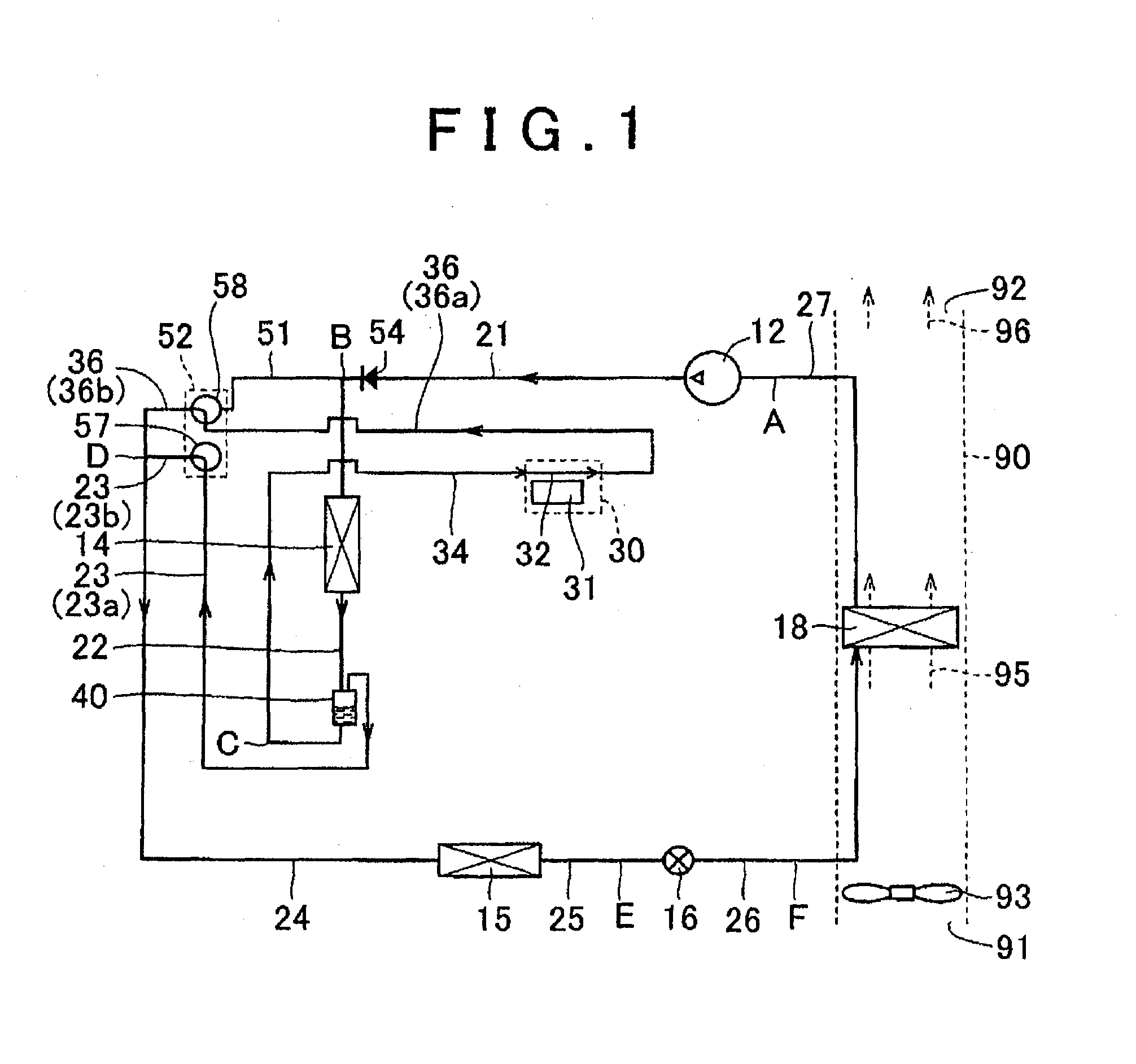
[0035]FIG. 1 is a schematic view that shows the configuration of a cooling system 1 according to a first embodiment. As shown in FIG. 1, the cooling system 1 includes a vapor compression refrigeration cycle 10. The vapor compression refrigeration cycle 10 is, for example, mounted on a vehicle in order to cool the cabin of the vehicle. Cooling with the use of the vapor compression refrigeration cycle 10 is performed, for example, when a switch for cooling is turned on or when an automatic control mode in which the temperature in the cabin of the vehicle is automatically adjusted to a set temperature is selected and the temperature in the cabin is higher than the set temperature.

[0036]The vapor compression refrigeration cycle 10 includes a compressor 12, a heat exchanger 14 that serves as a first heat exchanger, a heat exchanger 15, an expansion valve 16 that is an example of a decompressor, and a heat exchanger 18 that serves as a second heat exchanger.

[0037]The compressor 12 is actu...

second embodiment

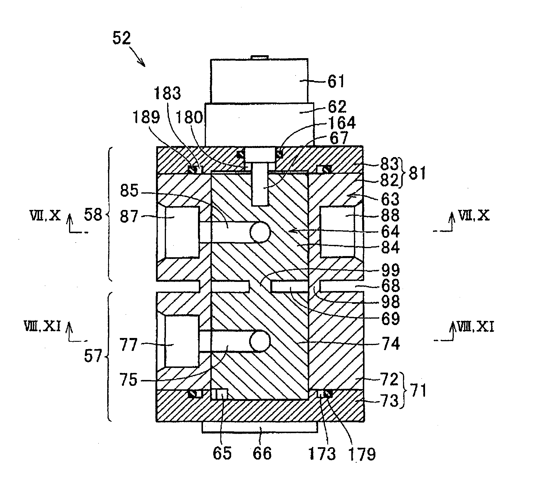
[0140]FIG. 12 is a cross-sectional view that shows the details of a selector valve 52 according to a second embodiment. The selector valve 52 according to the second embodiment differs from the selector valve 52 according to the first embodiment shown in FIG. 3 in that a heat insulating material 169 is provided in the space 69 between the valve elements 74 and 84, a heat insulating material 168 is provided in the space 68 between the sleeve portions 72 and 82 and a heat insulating material providing space is formed between the valve 57 and the valve 58.

[0141]That is, the valve element heat insulating unit that suppresses transfer of heat from the valve element 84 to the valve element 74 may be the hollow space 69 or may have a configuration such that the heat insulating material 169 is provided inside the space 69. The housing heat insulating unit that suppresses transfer of heat from the second housing 81 to the first housing 71 may be the hollow space 68 or may have a configuratio...

third embodiment

[0143]FIG. 13 is a cross-sectional view that shows a selector valve 52 according to a third embodiment. The selector valve 52 according to the third embodiment differs from that of the first embodiment described with reference to FIG. 7 in that the diameter of the through-hole 85 formed in the valve element 84 is increased.

[0144]In the first embodiment, the through-hole 85 is formed such that, at the openings 85a and 85b at which the through-hole 85 is open at the outer periphery of the valve element 84, the diameter of the through-hole 85 is equal to the diameter of each of the radial holes 86 and 87, the diameter of the flow passage of refrigerant flowing from the radial hole 86 to the through-hole 85 does not change and the diameter of the flow passage of refrigerant flowing from the through-hole 85 to the radial hole 87 does not change. In contrast to this, in the third embodiment, the through-hole 85 is formed such that, at the openings 85a and 85b, the through-hole 85 has a la...


PUM


Abstract

A selector valve includes: a first valve element having a through-hole; a first housing having a radial hole through which fluid flowing though the through-hole passes, the first housing accommodating the first valve element; a second valve element having a through-hole; a second housing having radial holes through which fluid flowing through the through-hole passes, the second housing accommodating the second valve element; and a motor configured to integrally actuate the first valve element and the second valve element. A hollow space configured to suppress transfer of heat between the first valve element and the second valve element is formed between the first valve element and the second valve element. A hollow space configured to suppress transfer of heat between the first housing and the second housing is formed between the first housing and the second housing.

Description

BACKGROUND OF THE INVENTION[0001]1. Field of the Invention[0002]The invention relates to a selector valve and a cooling system and, more particularly, to a selector valve that switches a flow passage of fluid and a cooling system that includes the selector valve.[0003]2. Description of Related Art[0004]In recent years, hybrid vehicles, fuel cell vehicles, electric vehicles, and the like, that travel with the use of driving force of a motor become a focus of attention as one of measures against environmental issues. In such vehicles, electrical devices, such as a motor, a generator, an inverter, a converter and a battery, exchange electric power to generate heat. Therefore, these electrical devices need to be cooled.[0005]Japanese Patent Application Publication No. 2000-73763 (JP 2000-73763 A) describes a hybrid vehicle cooling system that includes a first cooling circuit that cools an engine cylinder head and a driving motor selectively or simultaneously, a second cooling circuit th...

Claims


Application Information

Patent Timeline
IPC IPC(8): F16K11/085F25B41/04
CPCF16K11/085F25B41/04B60H1/00485F16K11/0856F25B41/20F25B2400/23F25B23/006F25D19/00Y10T137/86871
Inventor OHNO, YUICHIUCHIDA, KAZUHIDEJOJIMA, YUKIKAWAKAMI, YOSHIAKITAKAHASHI, EIZOSATO, KOUSUKE
Owner TOYOTA JIDOSHA KK
Why Eureka
Try Eureka