
Stator and gap winding motor using the same

a gap winding motor and stator technology, applied in windings, windings, windings insulation materials, etc., can solve the problems of increasing cost, reducing the number of constituent parts, and generating noise. noise, the effect of reducing the size of the motor

Inactive Publication Date: 2008-10-02
YASKAWA DENKI KK
View PDF3 Cites 9 Cited by
  • Summary
  • Abstract
  • Description
  • Claims
  • Application Information

AI Technical Summary

Benefits of technology

[0017]Preferred embodiments of the present invention have been developed in view of the above-mentioned and / or other problems in the related art. The preferred embodiments of the present invention can significantly improve upon existing methods and / or apparatuses.
[0018]Among other potential advantages, some embodiments can provide a stator capable of reducing the size and cost thereof while preventing a rotor detector from being affected by noise generated from a stator coil connection portion.
[0019]Among other potential advantages, some embodiments can provide the so-called gap winding motor capable of reducing the size and cost thereof while preventing a rotor detector from being affected by noise generated from a stator coil connection portion.

Problems solved by technology

However, this document is directed to a special type of a stator which easily generates noise.
As explained above, in a conventional motor of this type, since the rotation detector printed circuit board 44 is arranged outside the stator 41, it was difficult to reduce the size of the motor and decrease the number of constituent parts, resulting in increased cost.

Method used


Image

  • Stator and gap winding motor using the same
  • Stator and gap winding motor using the same
  • Stator and gap winding motor using the same

Examples


Embodiment Construction

[0035]In the following paragraphs, some embodiments of the invention will be described by way of example and not limitation. It should be understood based on this disclosure that various other modifications can be made by those in the art based on these illustrated embodiments.

[0036]Hereinafter, an embodiment of the present invention will be explained with reference to the attached drawings.

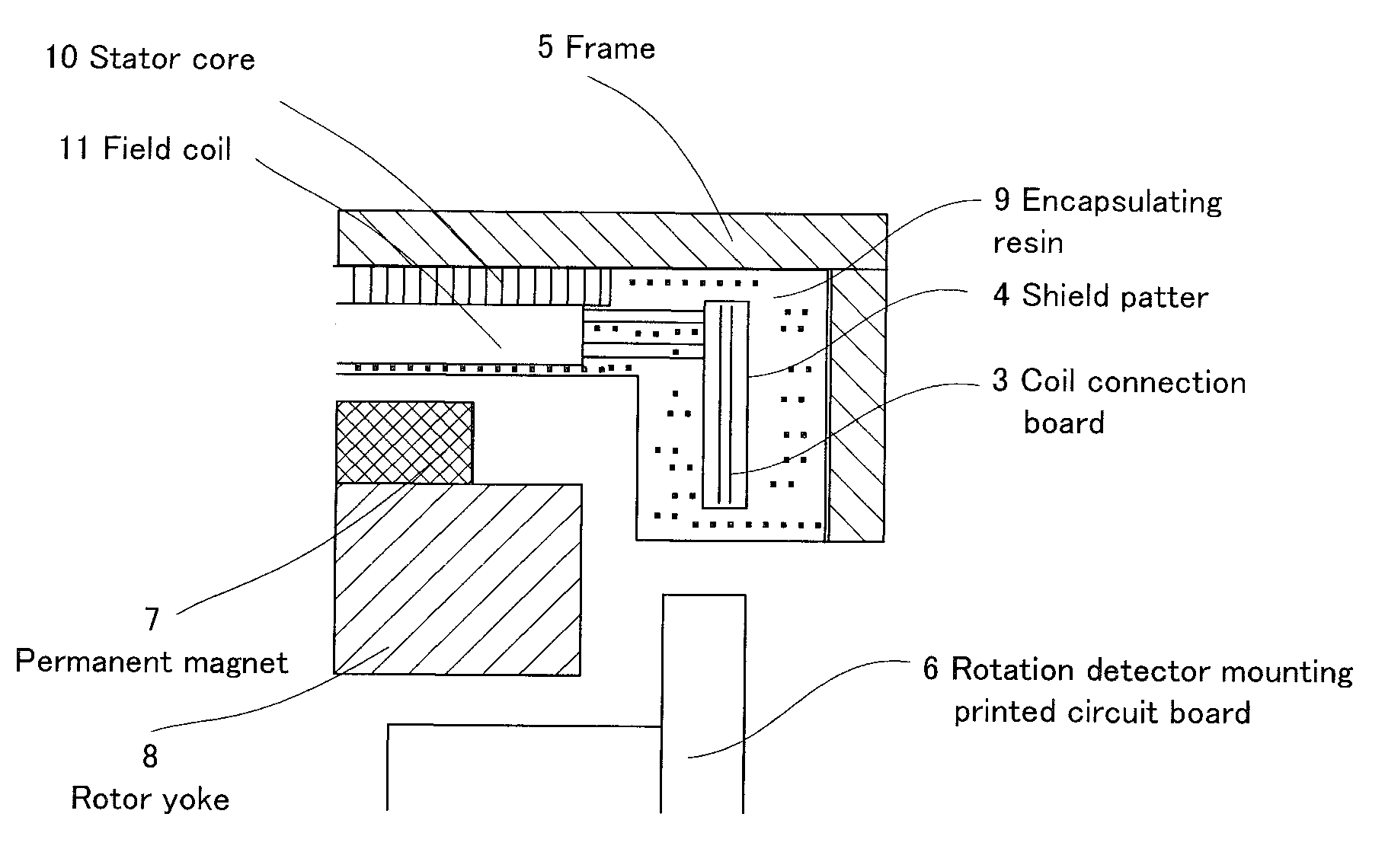
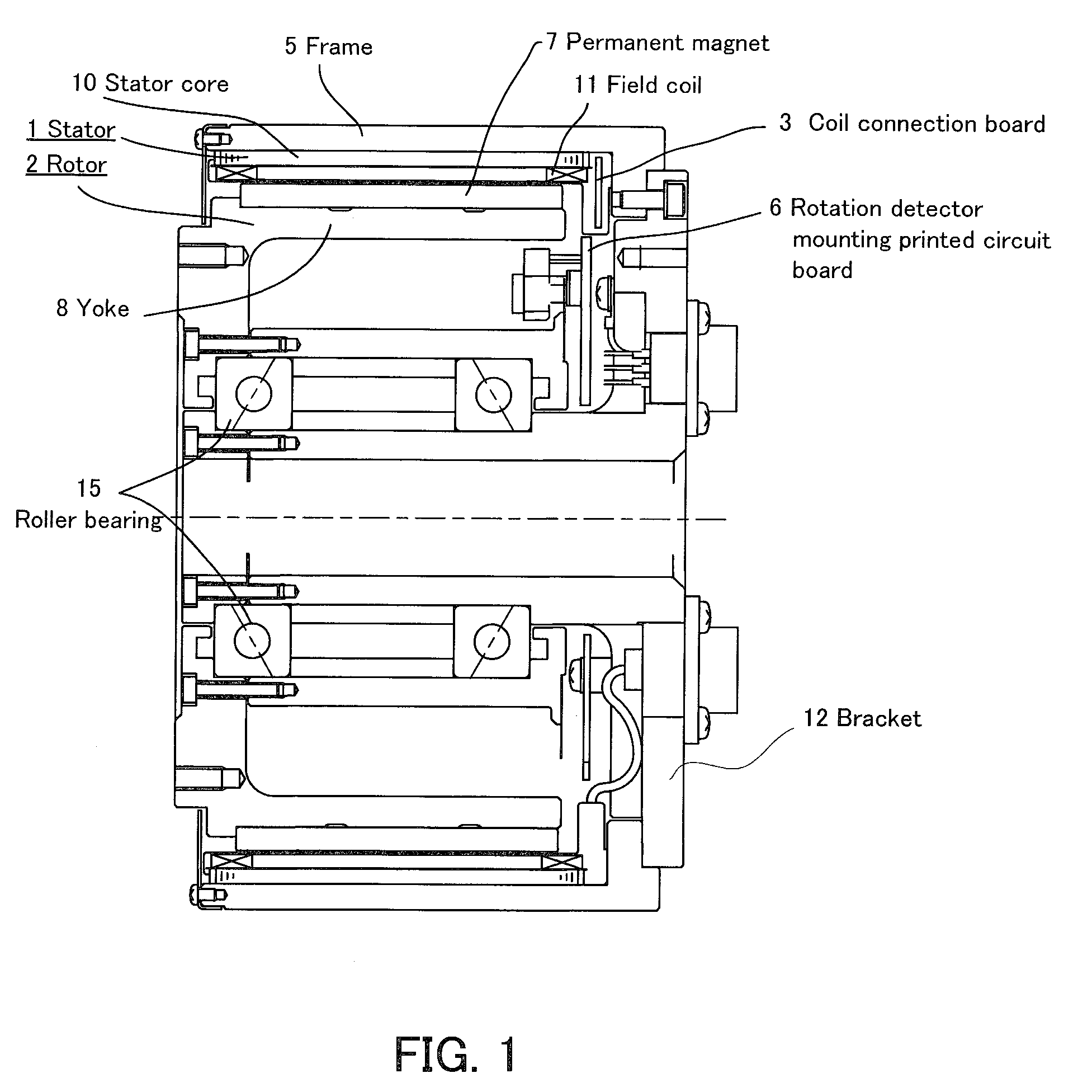
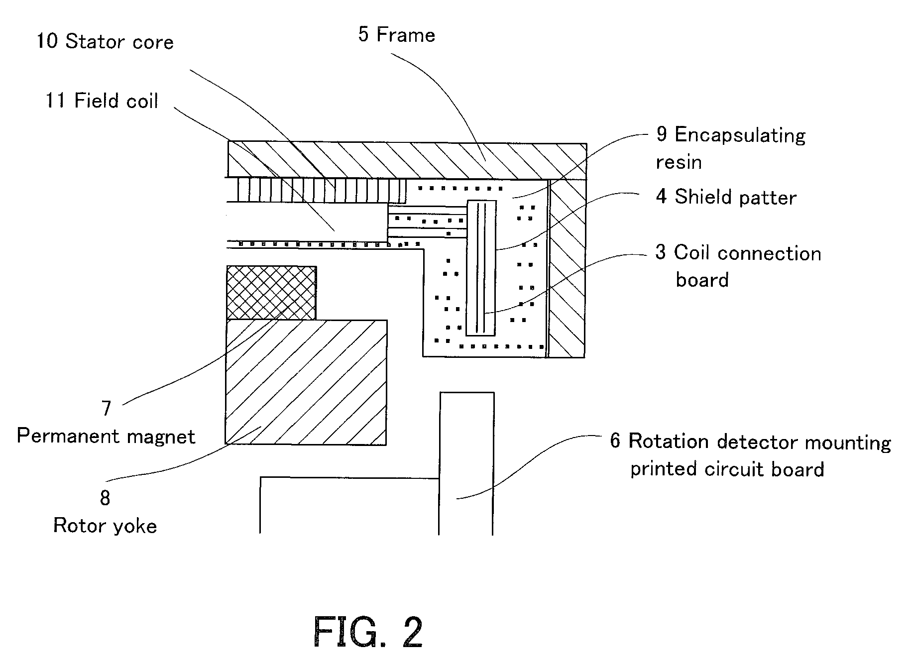
[0037]FIG. 1 is a vertical schematic cross-sectional view showing the so-called gap winding motor according to an embodiment of the present invention. FIG. 1 shows the positional relation of a stator 1, a coil connection board 3 arranged within the stator 1, and a rotation detector mounting printed circuit board 6. This motor includes the stator 1 and a rotor 2 rotatably supported at the inner side of the stator 1 via roller bearings 15. The rotor 2 is constituted by a yoke 8 having a cylindrical permanent magnet arranging surface and permanent magnets 7 arranged at equal intervals on the surface...


PUM


Abstract

A so-called gap winding motor capable of preventing a rotation detector from being affected by noise generated by a stator coil connection portion and decreasing the size and cost is provided. The gap winding motor comprises a stator including a stator core, a plurality of stator coils arranged on an inner peripheral surface of the stator core, a ring-shaped coil connection board configured to connect the plurality of stator coils, and ring-shaped shield patterns provided at both surfaces of the ring-shaped coil connection board. The stator core, the coil connection board, and the shield patterns are encapsulated with resin, and a rotation detector mounting printed circuit board is arranged in a gap located at an inner side of the stator core.

Description

RELATED APPLICATIONS[0001]This application claims priority under 35 U.S.C. §119 to Japanese Patent Application No. 2007-095444 filed on Mar. 30, 2007. The entire disclosure of the application is incorporated herein by reference in its entirety.BACKGROUND OF THE INVENTION[0002]1. Field of the Invention[0003]The present invention relates to a stator for a flat armature winding type brushless DC motor, the so-called gap winding type electric motor, for use in FA (Factory Automation) and OA (Office Automation), and the gap winding type electric motor using the stator.[0004]2. Description of Related Art[0005]The following description sets forth the inventor's knowledge of related art and problems therein and should not be construed as an admission of knowledge in the prior art.[0006]In a conventional electric motor, a rotation detector is arranged at a position sufficiently distant from the motor electromagnetic portion. For example, such a rotation detector is attached to the non-load s...

Claims


Application Information

Patent Timeline
Patent Type & Authority Applications(United States)
IPC IPC(8): H02K3/50H02K21/12
CPCH02K3/30H02K3/47H02K15/12H02K29/06
Inventor MIYAMOTO, TAKASHI
Owner YASKAWA DENKI KK
Learn More